Dell Brocade 6520 Brocade 6520 Hardware Referencce Manual - Page 29
Brocade 6520 Operation, In this LED activity interpretation, Brocade 6520 LEDs, LED locations
 |
View all Dell Brocade 6520 manuals
Add to My Manuals
Save this manual to your list of manuals |
Page 29 highlights
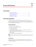
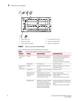
Brocade 6520 Operation Chapter 3 In this chapter •LED activity interpretation 17 •POST and boot-up specifications 21 •Interpreting POST results 22 •Brocade 6520 maintenance 22 •Brocade 6520 management 24 LED activity interpretation System activity and status can be determined through the activity of the LEDs on the switch. Sometimes, the LEDs flash either of the colors during boot, POST, or other diagnostic tests. This is normal; it does not indicate a problem unless the LEDs do not indicate a healthy state after all boot processes and diagnostic tests are complete. Brocade 6520 LEDs The Brocade 6520 has the following LEDs: • One system status LED (bicolor: green/amber). • One power status LED (green). • Two Ethernet port LEDs (green). • One port status LED for each port on the switch (bicolor: green/amber). These LEDs are arrayed above each pair of Fibre Channel ports. • Two power supply status LEDs per power supply (AC indicator is bicolor: green/amber and DC indicator is green). • One fan status LED per fan (bicolor: green/amber). NOTE The serial console port LEDs do not light up at any time, even when a cable is inserted and the link is active. LED locations Figure 3 shows the port side of the Brocade 6520. The port status LEDs for the FC ports are arranged left and right to correspond to the upper and lower ports in each pair. Refer to Figure 1 for the locations of the FC ports. Brocade 6520 Hardware Reference Manual 17 53-1002705-01
-
 1
1 -
2
-
3
-
4
-
5
-
6
-
7
-
8
-
9
-
10
-
11
-
12
-
13
-
14
-
15
-
16
-
17
-
18
-
19
-
20
-
21
-
22
-
23
-
 24
24 -
 25
25 -
 26
26 -
 27
27 -
 28
28 -
 29
29 -
 30
30 -
 31
31 -
 32
32 -
 33
33 -
 34
34 -
35
-
36
-
37
-
38
-
39
-
40
-
41
-
42
-
43
-
44
-
45
-
46
-
47
-
48
-
49
-
50
-
51
-
52
-
53
-
54
-
55
-
56
-
57
-
58
-
59
-
60
-
61
-
62
-
63
-
64
-
65
-
66
-
67
-
68
-
69
-
70
 |
 |