Dell Brocade 6520 Brocade 6520 Hardware Referencce Manual - Page 53
Memory specifications, Fibre Channel port specifications, Serial port specifications
 |
View all Dell Brocade 6520 manuals
Add to My Manuals
Save this manual to your list of manuals |
Page 53 highlights
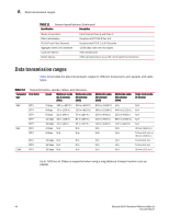
Memory specifications A Memory specifications The Brocade 6520 has three primary types of memory devices: boot flash, compact flash, and main memory. The size of each is listed in Table 13. TABLE 13 Brocade 6520 memory specifications Memory type Amount Boot flash Compact flash Main memory (DDR2 SODIMM) 4 MB 2 GB 2 GB, 400 MHz, 72-bit bus Fibre Channel port specifications The Fibre Channel ports in the Brocade 6520 are compatible with SWL, LWL, and ELWL SFP+ (for 16 Gbps performance) transceivers. The strength of the signal is determined by the type of transceiver in use. The ports meet all required safety standards. For more information about these standards, refer to "Regulatory compliance" on page 42. The ports are capable of operating at 2, 4, 8, or 16 Gbps depending on SFP+ transceiver models and are able to autonegotiate to the maximum link speed. The first eight ports on the switch can be configured to run at 10 Gbps with the appropriate license and transceivers. Serial port specifications The serial port is located on the port side of the switch. The Brocade 6520 uses an RJ45 connector for the serial port. An RJ45-to-RS-232 adapter is also provided with the switch. NOTE To protect the serial port from damage, keep the cover on the port when not in use. The serial port can be used to connect to a workstation to configure the switch IP address before connecting the switch to a fabric or IP network. The serial port's parameters are fixed at 9600 baud, 8 data bits, and no parity, with flow control set to None. Table 14 lists the serial cable pinouts. TABLE 14 Serial cable pinouts PIN Signal Description 1 Not supported 2 Not supported 3 UART1_TXD N/A N/A Transmit data 4 GND Logic ground 5 GND Logic ground Brocade 6520 Hardware Reference Manual 41 53-1002705-01
-
 1
1 -
2
-
3
-
4
-
5
-
6
-
7
-
8
-
9
-
10
-
11
-
12
-
13
-
14
-
15
-
16
-
17
-
18
-
19
-
20
-
21
-
22
-
23
-
24
-
25
-
26
-
27
-
28
-
29
-
30
-
31
-
32
-
33
-
34
-
35
-
36
-
37
-
38
-
39
-
40
-
41
-
42
-
43
-
44
-
45
-
46
-
47
-
 48
48 -
 49
49 -
 50
50 -
 51
51 -
 52
52 -
 53
53 -
 54
54 -
 55
55 -
 56
56 -
 57
57 -
 58
58 -
59
-
60
-
61
-
62
-
63
-
64
-
65
-
66
-
67
-
68
-
69
-
70
 |
 |