Dell Brocade 6520 Brocade 6520 Hardware Referencce Manual - Page 39
Removal and Replacement of Power Supplies and Fans, In
 |
View all Dell Brocade 6520 manuals
Add to My Manuals
Save this manual to your list of manuals |
Page 39 highlights
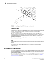
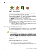
Chapter 4 Removal and Replacement of Power Supplies and Fans In this chapter •Removal and replacement introduction 27 •Power supply removal and replacement 28 •Fan removal and replacement 31 •SFP+ transceiver removal and replacement 35 Removal and replacement introduction NOTE Read the "Installation and safety considerations" before servicing. The field-replaceable units (FRUs) in the Brocade 6520 can be removed and replaced without special tools. The Brocade 6520 can continue operating during the FRU replacement if the conditions specified in the procedures are followed. DANGER The procedures in this manual are for qualified service personnel. Before beginning replacement CAUTION This document describes how to change field-replaceable units (FRUs) for units with either a port-side air exhaust or a port-side air intake. You must replace a failed unit with the same type of unit. This applies to both power supplies and fans. A new FRU must have the same part number (P/N) as the FRU being replaced. The manufacturing P/N is located on the top of the FRU. You can use external labels as a guide. Refer to Figure 7. Both the power supply and fan FRUs are labeled with an airflow symbol on the faceplate to indicate whether the assembly takes in or exhausts air. The label also appears on the top of the assembly. ATTENTION All fans and power supplies must have the same airflow symbol (E or I) to be compatible with each other. Brocade 6520 Hardware Reference Manual 27 53-1002705-01
-
 1
1 -
2
-
3
-
4
-
5
-
6
-
7
-
8
-
9
-
10
-
11
-
12
-
13
-
14
-
15
-
16
-
17
-
18
-
19
-
20
-
21
-
22
-
23
-
24
-
25
-
26
-
27
-
28
-
29
-
30
-
31
-
32
-
33
-
 34
34 -
 35
35 -
 36
36 -
 37
37 -
 38
38 -
 39
39 -
 40
40 -
 41
41 -
 42
42 -
 43
43 -
 44
44 -
45
-
46
-
47
-
48
-
49
-
50
-
51
-
52
-
53
-
54
-
55
-
56
-
57
-
58
-
59
-
60
-
61
-
62
-
63
-
64
-
65
-
66
-
67
-
68
-
69
-
70
 |
 |