Dell Brocade 6520 Brocade 6520 Hardware Referencce Manual - Page 43
Fan removal and replacement
 |
View all Dell Brocade 6520 manuals
Add to My Manuals
Save this manual to your list of manuals |
Page 43 highlights
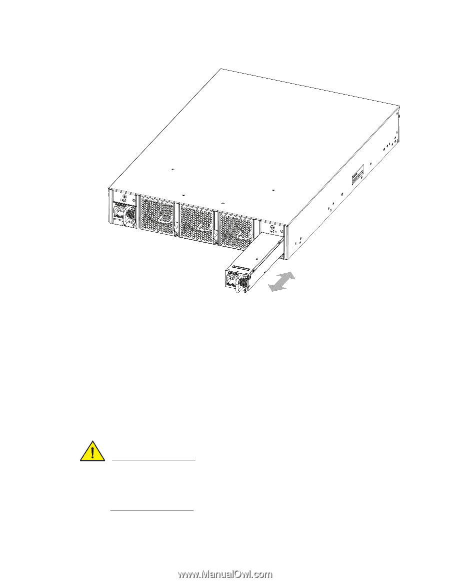
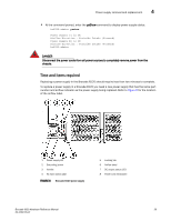
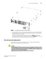
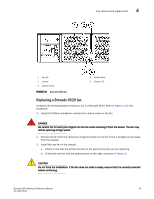
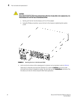
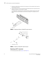
Fan removal and replacement 4 FIGURE 9 Inserting the power supply in the Brocade 6520 6. Verify that the LEDs on the new power supply display steady green while the Brocade 6520 is operating (refer to Table 8). If the LEDs are not steady green, ensure that the power supply is securely installed and seated properly. Optionally, if using the command line interface (CLI), enter the psShow command at the command line prompt to display the status. You can also use the chassisShow command. The power supply status can also be viewed using the Web Tools application. Fan removal and replacement The Brocade 6520 has three fans as displayed in Figure 2. The Fabric OS identifies the fan locations from left to right as fan #3, fan #2, and fan #1. CAUTION Disassembling any part of the fan voids the part warranty and regulatory certifications. There are no user-serviceable parts inside the fan. Because the cooling system relies on pressurized air, do not leave any of the fan slots empty longer than two minutes while the switch is operating. If a fan fails, leave it in the switch until it can be replaced. Maintain all three fans in operational condition to provide redundancy. Brocade 6520 Hardware Reference Manual 31 53-1002705-01
-
 1
1 -
2
-
3
-
4
-
5
-
6
-
7
-
8
-
9
-
10
-
11
-
12
-
13
-
14
-
15
-
16
-
17
-
18
-
19
-
20
-
21
-
22
-
23
-
24
-
25
-
26
-
27
-
28
-
29
-
30
-
31
-
32
-
33
-
34
-
35
-
36
-
37
-
 38
38 -
 39
39 -
 40
40 -
 41
41 -
 42
42 -
 43
43 -
 44
44 -
 45
45 -
 46
46 -
 47
47 -
 48
48 -
49
-
50
-
51
-
52
-
53
-
54
-
55
-
56
-
57
-
58
-
59
-
60
-
61
-
62
-
63
-
64
-
65
-
66
-
67
-
68
-
69
-
70
 |
 |