Dell Brocade 6520 Brocade 6520 Hardware Referencce Manual - Page 32
Table 8
 |
View all Dell Brocade 6520 manuals
Add to My Manuals
Save this manual to your list of manuals |
Page 32 highlights
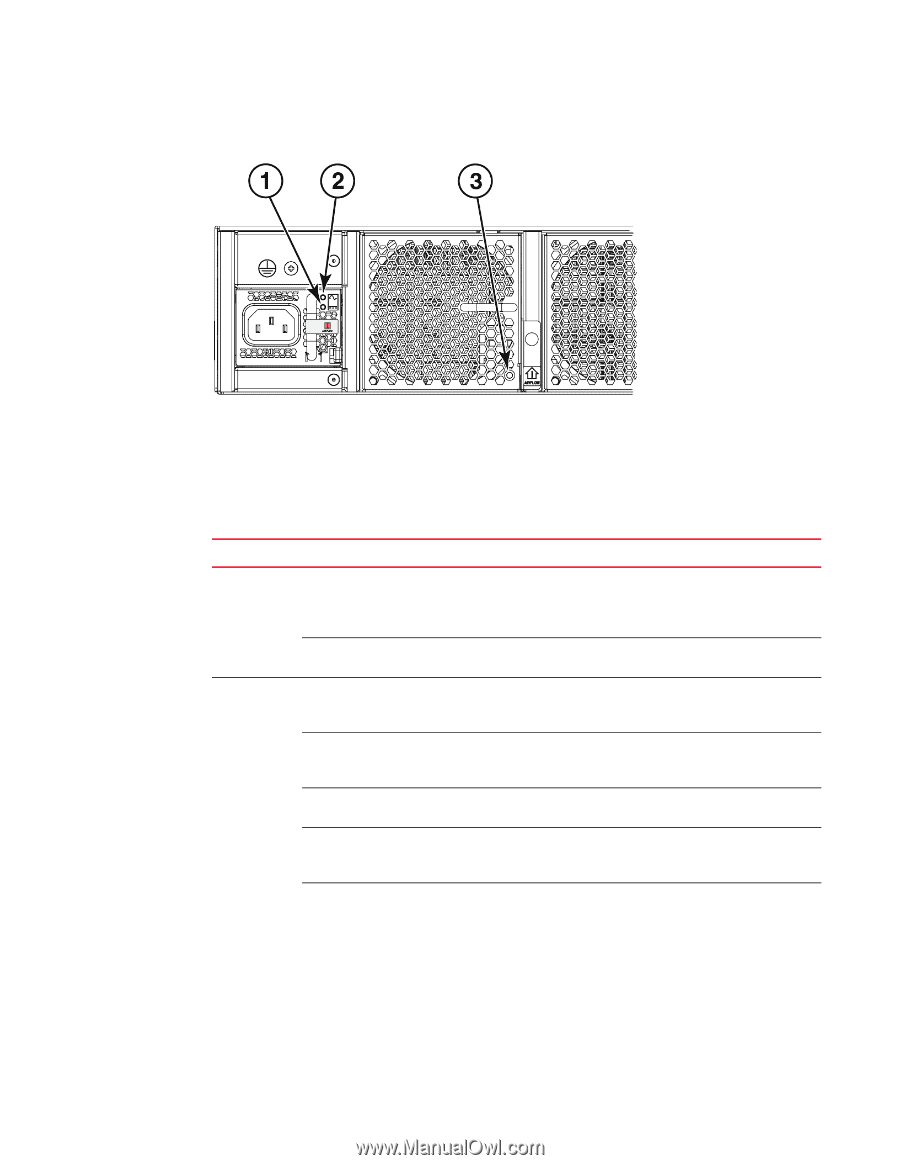
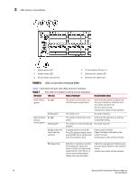
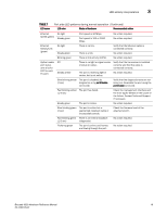
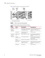
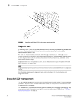
3 LED activity interpretation Figure 4 shows the LEDs on the non-port side of the switch. 1 Power supply DC status LED 2 Power supply AC status LED 3 Fan status LED FIGURE 4 LEDs on non-port side of Brocade 6520 Table 8 describes the LEDs on the non-port side of the switch. TABLE 8 Non-port side LED patterns during normal operation LED name LED color Status of hardware Recommended action Power supply AC input status (one green LED) No light Power supply is not receiving AC input voltage or AC input voltage is below operational limit. Verify that the power supply is properly seated and the power cord is connected to a functioning AC power source. Steady green AC input voltage is within operational range. No action required. Power supply DC output status (one bi-color LED) Flashing amber (1:1) Flashing amber/green (2:1) Flashing amber/green (1:1) Output voltage is not enabled. Over temperature warning. Internal fan is out of regulation. Verify that the power supply is fully seated and that the captive screw is secured. Verify that ambients temperature is less than 40C and check for intake airflow blockage. Replace the power supply. Steady amber Steady green Power supply is faulty or not plugged in completely. DC output OK. Check the power cord, current, voltage, and temperature to determine the problem. No action required. 20 Brocade 6520 Hardware Reference Manual 53-1002705-01
-
 1
1 -
2
-
3
-
4
-
5
-
6
-
7
-
8
-
9
-
10
-
11
-
12
-
13
-
14
-
15
-
16
-
17
-
18
-
19
-
20
-
21
-
22
-
23
-
24
-
25
-
26
-
 27
27 -
 28
28 -
 29
29 -
 30
30 -
 31
31 -
 32
32 -
 33
33 -
 34
34 -
 35
35 -
 36
36 -
 37
37 -
38
-
39
-
40
-
41
-
42
-
43
-
44
-
45
-
46
-
47
-
48
-
49
-
50
-
51
-
52
-
53
-
54
-
55
-
56
-
57
-
58
-
59
-
60
-
61
-
62
-
63
-
64
-
65
-
66
-
67
-
68
-
69
-
70
 |
 |