Dell FC4500 Reference Guide
Dell FC4500 Manual
 |
View all Dell FC4500 manuals
Add to My Manuals
Save this manual to your list of manuals |
Dell FC4500 manual content summary:
- Dell FC4500 | Reference Guide - Page 1
EMC Enterprise Storage EMC Fibre Channel Disk-Array Processor Enclosure (DPE) Rackmount FC4500 HARDWARE REFERENCE P/N 014002901-04 EMC Corporation 171 South Street, Hopkinton, MA 01748-9103 Corporate Headquarters: (508) 435-1000, (800) 424-EMC2 Fax: (508) 435-5374 Service: (800) SVC-4EMC - Dell FC4500 | Reference Guide - Page 2
software programs described herein. EMC EMC Storage Logic, Universal Data Tone, E-Infostructure, Celerra , and Access Logix are trademarks of EMC Corporation. All other trademarks used herein are the property of their respective owners. ii EMC Fibre Channel Disk-Array Processor Enclosure (DPE - Dell FC4500 | Reference Guide - Page 3
frequency energy and, if not installed and used in accordance with the instruction manual, may cause harmful interference to radio communications. Operation of this equipment in EN55022, CISPR22 and AS/NZS 3548 Class A. EMC Fibre Channel Disk-Array Processor Enclosure (DPE) Hardware Reference iii - Dell FC4500 | Reference Guide - Page 4
iv EMC Fibre Channel Disk-Array Processor Enclosure (DPE) Hardware Reference - Dell FC4500 | Reference Guide - Page 5
Contents Preface...xi Chapter 1 Chapter 2 About the Rackmount Disk-Array Processor Enclosure Introduction 1-2 DPE Components 1-4 Enclosure 1-4 Midplane 1-8 Storage Processors (SPs 1-9 Link Control Cards (LCCs 1-11 Disk Modules 1-12 Disk Drives 1-12 Drive Carrier 1-13 Power Supplies 1-13 - Dell FC4500 | Reference Guide - Page 6
Size and Weight A-2 Drive Type A-3 SP Optical Cabling A-3 LCC Copper Cabling A-3 Standards Certification and Compliance A-3 Operating Limits A-5 Shipping and Storage Requirements A-6 Glossary ...g-1 Index ...i-1 vi EMC Fibre Channel Disk-Array Processor Enclosure (DPE) Hardware Reference - Dell FC4500 | Reference Guide - Page 7
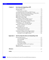
to a DPE 2-14 2-10 Cabling a DPE to a DAE 2-15 3-1 Status Lights Visible from the Front of the DPE 3-2 3-2 Unlocking and Opening the Front Door 3-10 3-3 Removing a Disk Filler Module 3-11 3-4 Removing a Disk Module 3-11 3-5 Installing a Disk Module 3-12 EMC Fibre Channel Disk-Array Processor - Dell FC4500 | Reference Guide - Page 8
Module 3-40 3-30 Removing the Bottom Power-Supply Module 3-41 3-31 Installing the Bottom Power Supply 3-42 3-32 Installing the Top Power Supply 3-43 3-33 Plugging in the AC Line Cord and Turning on Power 3-44 viii EMC Fibre Channel Disk-Array Processor Enclosure (DPE) Hardware Reference - Dell FC4500 | Reference Guide - Page 9
Tables 3-1 Status Lights Color Codes, Front of DPE 3-2 3-2 Status Lights Color Codes, Back of DPE 3-3 EMC Fibre Channel Disk-Array Processor Enclosure (DPE) Hardware Reference ix - Dell FC4500 | Reference Guide - Page 10
Tables x EMC Fibre Channel Disk-Array Processor Enclosure (DPE) Hardware Reference - Dell FC4500 | Reference Guide - Page 11
How This Manual Is Organized This manual describes how to install the EMC Fibre Channel Disk-Array Processor Enclosure (DPE) Rackmount Model FC4500, and how to replace and add customer-replaceable units (CRUs). If you will install and service the rackmount DPE, you should read this manual. After - Dell FC4500 | Reference Guide - Page 12
would type, displayed text, or program listings. For example: Fixed italic QUERY [CUU=cuu|VOLSER=volser] Arguments used in examples of command line syntax. xii EMC Fibre Channel Disk-Array Processor Enclosure (DPE) Hardware Reference - Dell FC4500 | Reference Guide - Page 13
1 About the Rackmount Disk-Array Processor Enclosure Topics in this chapter include: • Introduction 1-2 • DPE Components 1-4 • Link Control Cards (LCCs 1-11 • Redundancy in Configurations 1-17 About the Rackmount Disk-Array Processor Enclosure 1-1 - Dell FC4500 | Reference Guide - Page 14
-AL serial cabling, the FC4500 DPE can support up to 11 DAEs A DAE is a basic enclosure without a storage processor (SP). The FC4500 and 11 DAEs support up to 120 disk modules in a single disk-array file storage system. 1-2 EMC Fibre Channel Disk-Array Processor Enclosure (DPE) Hardware Reference - Dell FC4500 | Reference Guide - Page 15
Rackmount Disk-Array Processor Enclosure 1 You can place the DAEs in the same cabinet as the DPE, or in one or more separate cabinets. The DPE connects to the external Fibre Channel environment using GBIC connectors on the storage processor. High-availability features are standard. The EMC Access - Dell FC4500 | Reference Guide - Page 16
, front door, and slots for the SPs, LCCs, disk modules, power supplies, and fan packs. The following figures show the DPE components. Details on each component follow the figures. If the enclosure provides slots for two 1-4 EMC Fibre Channel Disk-Array Processor Enclosure (DPE) Hardware Reference - Dell FC4500 | Reference Guide - Page 17
the Rackmount Disk-Array Processor Enclosure 1 identical components, the component in slot A is called component-name A. If there is a second component, it is in slot B and is called component-nameB, as follows. Component SP LCC Power supply Name in Slot A SP A LCC A PS A Name in Slot B SP B LCC - Dell FC4500 | Reference Guide - Page 18
About the Rackmount Disk-Array Processor Enclosure 1 Front panel with door removed for clarity SP fan pack SP fan pack cover Figure 1-3 DPE Front View with SP Fan Cover and Door Removed 1-6 EMC Fibre Channel Disk-Array Processor Enclosure (DPE) Hardware Reference - Dell FC4500 | Reference Guide - Page 19
About the Rackmount Disk-Array Processor Enclosure 1 LCC A with expansion connector (marked EXP) Drive fan pack SP retaining screw (2 per SP) LCC B with expansion connector (marked EXP) Figure 1-4 DPE Back View SP B SP ejector (2 per SP) SP A ac line cord connectors Power supply PS A Power - Dell FC4500 | Reference Guide - Page 20
About the Rackmount Disk-Array Processor Enclosure 1 Front Panel SP A works with LCC A to run SP A's disk modules; SP B works with LCC B to run SP B's disk modules. Enclosure address light (0 for a DPE) Disk module status lights (two per module) Check Active DPE status lights Check Power 0 - Dell FC4500 | Reference Guide - Page 21
Disk-Array Processor Enclosure 1 The front door must be closed for the DPE to be EMI compliant. Opening the door to access the disk modules is a service disk modules. Storage Processors (SPs) The SP is the DPE's intelligent component. It defines the DPE and differentiates the DPE from a DAE. An SP - Dell FC4500 | Reference Guide - Page 22
is called the SP back end. The SP also has an Console connector (with a terminal icon), a connector for communication with the standby power supply, marked SPS, and a LAN connection. Each SP has four status lights 1-10 EMC Fibre Channel Disk-Array Processor Enclosure (DPE) Hardware Reference - Dell FC4500 | Reference Guide - Page 23
About the Rackmount Disk-Array Processor Enclosure 1 visible from the back of the DPE. For a definition of these light colors, see the "Monitoring DPE Status" section in Chapter 3. If a DPE has one SP, you can install a second one while the DPE is running.When both SPs are installed, you can replace - Dell FC4500 | Reference Guide - Page 24
(PLDA) profile The disk module slots in the enclosure accommodate drives with heights of either 2.54 cm (1.0 inch) or 4.06 cm (1.6 inches). You can combine drives of either height, and from different manufacturers, 1-12 EMC Fibre Channel Disk-Array Processor Enclosure (DPE) Hardware Reference - Dell FC4500 | Reference Guide - Page 25
Disk-Array Processor Enclosure 1 within the same DPE, subject to the restrictions imposed by the Core Software running in the DPE's SPs. The disk-drive carrier is a plastic assembly that slides into the enclosure slot guides switch. Each supply supports a fully configured DPE and shares load currents - Dell FC4500 | Reference Guide - Page 26
operation to minimize acoustic noise. If a fan fails, the voltage and speed of the remaining fans increase to compensate, resulting in higher acoustic noise. 1-14 EMC Fibre Channel Disk-Array Processor Enclosure (DPE) Hardware Reference - Dell FC4500 | Reference Guide - Page 27
About the Rackmount Disk-Array Processor Enclosure 1 ! Check light (amber) Latches Latches Figure 1-12 Drive Fan Pack The drive fan pack has one status light. The status light is described in the "Monitoring DPE Status" section of Chapter 3. Latches on the drive fan pack hold the pack in place. - Dell FC4500 | Reference Guide - Page 28
can remove the SP fan pack while the DPE is powered up. If the pack is removed for more than approximately two minutes, the SPs and disk modules power down. The SPs and disk modules power up when you reinstall the SP fan pack. 1-16 EMC Fibre Channel Disk-Array Processor Enclosure (DPE) Hardware - Dell FC4500 | Reference Guide - Page 29
About the Rackmount Disk-Array Processor Enclosure 1 Redundancy in Configurations Mirrored storage-system write caching requires: • Two SPs with equal memory of at least 128 Mbytes • Two power supplies • Two LCCs in the DPE and each DAE • Disks in slots 0:0 through 0:8 • SPS (standby power supply) - Dell FC4500 | Reference Guide - Page 30
About the Rackmount Disk-Array Processor Enclosure 1 What Next? Continue to the next chapter, which explains how to install a DPE. 1-18 EMC Fibre Channel Disk-Array Processor Enclosure (DPE) Hardware Reference - Dell FC4500 | Reference Guide - Page 31
system to provide internally regulated power. Typical values will be less, depending on the number and manufacturer of disk drives. These values represent either the values for the power cord of a DPE with a single power supply, or the total values shared by the line cords of two power supplies in - Dell FC4500 | Reference Guide - Page 32
. The DPE has a fixed EA of 0 that you cannot change. If you cable any DAEs to the DPE, you might want to set the nearest DAE's EA to 1, the next to 2, and so on. The enclosure address is displayed in lights visible behind the front door. 2-2 EMC Fibre Channel Disk-Array Processor Enclosure (DPE - Dell FC4500 | Reference Guide - Page 33
). You set the SP FC-AL address ID using switches, as explained later in this chapter. Enclosure Address (EA) Each DPE and DAE on a identifies the enclosure and determines disk module addresses. The DPE has a fixed EA of 0 that you cannot change. If you cable any DAEs to the DPE, you might want to - Dell FC4500 | Reference Guide - Page 34
mounting rails in the cabinet is explained in a rails installation manual shipped with the rails. 1. In the cabinet, set the help, lift the DPE and, from the front of the cabinet, slide the DPE onto the lowest rails. 2-4 EMC Fibre Channel Disk-Array Processor Enclosure (DPE) Hardware Reference - Dell FC4500 | Reference Guide - Page 35
door as shown below. Installing a Rackmount DPE 2 A. If the door is locked: ITnusrenrtthtehekekyey18in0toheclodcokowr'issela.tch. Remove the key from the latch, if desired. positioning it at a 45o angle to the enclosure, and snapping it into the hinge openings. Installing a DPE in a Cabinet 2-5 - Dell FC4500 | Reference Guide - Page 36
you use depends on where the rails are mounted in the cabinet. Figure 2-2 Securing the DPE to the Cabinet Front Channel 6. Secure the rear mounts of the DPE to the back channels of the cabinet, as shown in Figure 2-3. 2-6 EMC Fibre Channel Disk-Array Processor Enclosure (DPE) Hardware Reference - Dell FC4500 | Reference Guide - Page 37
the bracket at the back of each rail to the bottom left and right of the DPE using two screws (one per side). Figure 2-3 Securing the DPE to the Cabinet Back Channel 7. Close the DPE front door, as shown in Figure 2-4. The door must be closed for EMI compliance. Open the door only to service the DPE - Dell FC4500 | Reference Guide - Page 38
as follows: ITnusrenrtthtehekekyey18in0tohecoduonoter'rscllaotcckhw. ise. Remove the key, if desired. Latch Key To lock, turn 180o counterclockwise. Latch Figure 2-4 Closing and Locking the Front Door 2-8 EMC Fibre Channel Disk-Array Processor Enclosure (DPE) Hardware Reference - Dell FC4500 | Reference Guide - Page 39
(ALPA). Valid Fibre Channel address IDs range from 0 through 125 (decimal) (0 through 7D hexidecimal). Each SP's Fibre Channel address ID must be unique on the Fibre Channel loop. At the back of the DPE, for each SP use the SP FC-AL ID switches (see Figure 2-5) to set the address ID. Installing - Dell FC4500 | Reference Guide - Page 40
. . . 15 16 . . . 31 32 . . . 125 Left switch setting 0 0 . . . 0 1 . . . 1 2 . . . 7 Right switch setting 0 1 . . . F 0 . . . F 0 . . . D Figure 2-5 SP Fibre Channel Arbitrated Loop Address ID Switches (Back of SP) 2-10 EMC Fibre Channel Disk-Array Processor Enclosure (DPE) Hardware Reference - Dell FC4500 | Reference Guide - Page 41
Installing a Rackmount DPE 2 9. For access to the ac power inlets, you must remove the drive fan pack. Remove the drive fan pack as shown below. A. the cabinet, plug the ac line cord into each power supply and turn on the supply's power, as shown in Figure 2-7. Installing a DPE in a Cabinet 2-11 - Dell FC4500 | Reference Guide - Page 42
Installing a Rackmount DPE 2 Bottom power supply ac inlet ac power cord (right-angle plug Top power supply Channel ac power cord 2-7 Plugging the AC Line Cord into the Power Supply and Turning on the Power Switch 2-12 EMC Fibre Channel Disk-Array Processor Enclosure (DPE) Hardware Reference - Dell FC4500 | Reference Guide - Page 43
Reinstall the drive fan pack on the back of the DPE. You can install the drive fan pack in either horizontal clicks into place. Figure 2-8 Installing the Drive Fan Module 12. Attach the Fibre Channel cable from SP A and/or B Port to the external environment) as shown next. When working with optical - Dell FC4500 | Reference Guide - Page 44
GBIC connector and each fibre optic cable. B. Plug the fibre optic cable into Port A and/or Port B on the SP. Optical GBIC connector B A Cover Cover Figure 2-9 Attaching Optical Cables to a DPE Fibre optic cable 2-14 EMC Fibre Channel Disk-Array Processor Enclosure (DPE) Hardware Reference - Dell FC4500 | Reference Guide - Page 45
14. If the DPE has another SP, LCC, and DAE, connect the DPE's other LCC and the DAE's other LCC as above. 15. To connect additional DAEs, attach a copper cable between the DAE's LCC EXP connector and the next DAE's PRI (primary) connector (detailed in the DAE Installation Manual). If this DAE and - Dell FC4500 | Reference Guide - Page 46
to the ac distribution strips that supply the DPE. The power in the distribution strips may be controlled by a circuit breaker located inside the cabinet (if the cabinet has such breakers) or externally to the cabinet. 2-16 EMC Fibre Channel Disk-Array Processor Enclosure (DPE) Hardware Reference - Dell FC4500 | Reference Guide - Page 47
to go off and the fans to stop before proceeding with further service to the storage system. Never remove the fan pack and then shut off the power supply to shut down an DPE. Doing that effectively cuts out the SPS and write cache data cannot be saved to the vault drives, which - Dell FC4500 | Reference Guide - Page 48
DPE 2 Binding Disk Modules into Groups After cabling a DPE and any DAEs, you can bind disk modules into groups and set up storage-system caching. To bind disk modules and set up caching, you will use a utility described in the server setup or installation manual. 2-18 EMC Fibre Channel Disk-Array - Dell FC4500 | Reference Guide - Page 49
DPE Status 3-1 • Handling CRUs 3-4 • Power Issues and CRUs 3-4 • Avoiding Electrostatic Discharge (ESD) Damage 3-6 • Precautions When Removing, Installing, or Storing CRUs .........3-7 • Precautions When Handling Optical Cables 3-8 • Replacing or Adding a Disk Module 3-9 • Replacing the SP - Dell FC4500 | Reference Guide - Page 50
is not obvious from another fault light on the front, look at the back of the DPE. SP Fan Pack Check 1 Amber On when the SP fan pack is faulty (not visible with fan pack cover on; to remove cover, see page 3-14). 3-2 EMC Fibre Channel Disk-Array Processor Enclosure (DPE) Hardware Reference - Dell FC4500 | Reference Guide - Page 51
Servicing and Upgrading a DPE 3 Table 3-1 Status Lights Color Codes, Front of DPE (continued) Light Disk Active Disk Check DPE Active DPE Check SP Fan Pack Check Quantity Color 1 per disk module Green slot 1 per disk module Amber slot 1 Green 1 Amber 1 Amber Meaning Off when the module - Dell FC4500 | Reference Guide - Page 52
fan pack or SP fan pack while the DPE is powered up. If the pack is removed for more than two minutes, the SPs and disk modules power down. The SPs and disk modules power up when you reinstall the drive or SP fan pack. 3-4 EMC Fibre Channel Disk-Array Processor Enclosure (DPE) Hardware Reference - Dell FC4500 | Reference Guide - Page 53
of the cabinet, you do not have to use cabinet anti-tip devices when you upgrade or service a DPE. If you need to power down a DPE, either: • Shut down the main ac lines to the DPE, or • Remove the drive fan pack (described on page 3-35) and set the power switch on each power - Dell FC4500 | Reference Guide - Page 54
the equipment. Read and understand the following instructions. Emergency Procedures (Without an ESD Kit) all other materials you will need before you service a DPE. Once servicing begins, you should avoid moving away from EMC Fibre Channel Disk-Array Processor Enclosure (DPE) Hardware Reference - Dell FC4500 | Reference Guide - Page 55
Servicing and Upgrading a DPE 3 • Before touching any CRU, touch a bare (unpainted) metal surface an ESD wristband as follows: attach the clip of the ESD wristband to the ESD bracket or bare metal on the DPE enclosure, and put the wristband around your wrist with the metal button against your skin. - Dell FC4500 | Reference Guide - Page 56
Servicing and Upgrading a DPE 3 Precautions When support. • Do not pull long runs of cable. It is best to lay the cable in place or pull only a few feet at a time. • Run the cables so that they are not stepped on or rolled over by anything. 3-8 EMC Fibre Channel Disk-Array Processor Enclosure (DPE - Dell FC4500 | Reference Guide - Page 57
module available. The part number (PN005xxxxxx) appears on the top or bottom of the module. A replacement disk module should have the same format (52- byte-per-sector format is required for arrays) and the same capacity (size and speed) as the disk it is replacing. An add-on can be any capacity but - Dell FC4500 | Reference Guide - Page 58
the door open. Irfetinhsetadlol oitrbsynpaopssitoioffniitnsghiitnagteas,45o angle to the enclosure, and snapping it into the hinge openings. Figure 3-2 Unlocking and Opening the Front Door 3-10 EMC Fibre Channel Disk-Array Processor Enclosure (DPE) Hardware Reference - Dell FC4500 | Reference Guide - Page 59
Servicing and Upgrading a DPE 3 2. Locate the slot where you want to install the new or replacement disk module. 3. Remove the disk or disk filler module from the slot as shown below. Latch A. Grasp the filler module handle so your thumb is on the latch. B. Push the latch, and - Dell FC4500 | Reference Guide - Page 60
show that the Core Software has rediscovered the FC loop. 2. Remove and store the ESD wristband. The door must be closed for EMI compliance when the DPE is powered up. Open it only to replace or add a disk module. 3-12 EMC Fibre Channel Disk-Array Processor Enclosure (DPE) Hardware Reference - Dell FC4500 | Reference Guide - Page 61
Servicing and Upgrading a DPE 3 3. Close and lock the front door as shown below. A. Raise the door until it latches into place. Latch Key B. If the key, if desired. To lock, turn key 180o counterclockwise. Latch Figure 3-6 Closing and Locking the Front Door Replacing or Adding a Disk Module 3-13 - Dell FC4500 | Reference Guide - Page 62
. Removing the SP Fan 1. At the front of the DPE, grasp the SP fan pack cover at its sides Pack and pull it from its ballstud mounts as shown below. Ballstud Figure 3-7 Removing the SP Fan Pack Cover 2. Remove the fan pack as shown next. 3-14 EMC Fibre Channel Disk-Array Processor Enclosure - Dell FC4500 | Reference Guide - Page 63
Servicing and Upgrading a DPE 3 A. Slide the latches on the fan pack inward as shown, and hold them in. B. Grasp the handles and gently pull the pack from the enclosure. Figure 3-8 Removing the SP Fan Pack Installing the SP Fan Pack 1. At the front of the DPE, insert the replacement fan - Dell FC4500 | Reference Guide - Page 64
Servicing and Upgrading a DPE 3 LED Figure 3-9 Installing the Replacement SP Fan Pack 2. At the front of the deskside DPE, grasp the SP fan pack cover at its sides and push it onto its ballstud mounts with the louvers slanted downward as shown next. 3-16 EMC Fibre Channel Disk-Array Processor - Dell FC4500 | Reference Guide - Page 65
Servicing and Upgrading a DPE 3 Ballstud Figure 3-10 Installing the SP Fan Pack Cover Replacing an Optical GBIC ! CAUTION Use an ESD wristband. Removing an Optical GBIC Connector Before removing any cables, make note of which cables are connected to which SP ports. 1. Remove any optical - Dell FC4500 | Reference Guide - Page 66
Port B on the SP. B. Install protective covers on each optical GBIC connector and on each fibre optic cable. Optical GBIC connector B Cover A Cover Fibre optic cable Figure 3-11 Removing an Optical Cable from an SP 3-18 EMC Fibre Channel Disk-Array Processor Enclosure (DPE) Hardware Reference - Dell FC4500 | Reference Guide - Page 67
Servicing and Upgrading a DPE 3 2. Remove the optical GBIC connector(s) from the SP as shown below. B A While pressing inward on the retaining clips, pull the optical GBIC connector out of the SP. You may need to wiggle the connector to unseat it. Retaining clip Figure 3-12 Removing an Optical - Dell FC4500 | Reference Guide - Page 68
bottom. B. Push the optical GBIC connector into SP Port A and/or Port B until it is firmly seated and the retaining clips are engaged. A Alignment slot B Optical GBIC connector Figure 3-13 Installing an Optical GBIC Connector on an SP 3-20 EMC Fibre Channel Disk-Array Processor Enclosure (DPE - Dell FC4500 | Reference Guide - Page 69
Servicing and Upgrading a DPE 3 2. Install the appropriate optical cable(s) on the SP's optical GBIC connector(s) as previously noted and as shown below. A. Remove the protective covers on each optical GBIC connector and on each fibre optic cable. B. - Dell FC4500 | Reference Guide - Page 70
from the SP (see page 3-17 or page 3-21). c. If you are removing the SP to replace the memory module, remove the cables (see page 3-18 or page 3-21). 2. Remove the SP or filler module from its slot as shown next: 3-22 EMC Fibre Channel Disk-Array Processor Enclosure (DPE) Hardware Reference - Dell FC4500 | Reference Guide - Page 71
Servicing and Upgrading a DPE 3 Retaining screw (one each side) Ejector (one each side) A. Loosen the retaining screws. B. Simultaneously open the ejectors as far as they will go. C. Gently pull the SP or filler module from the enclosure, supporting it at its sides. D. If you removed an SP (not a - Dell FC4500 | Reference Guide - Page 72
on the SP or DPE enclosure; then put the wristband around your wrist with the metal button against your skin. 1. Remove the SP from the DPE (see page 3-23), and place it on a static-free work surface. 2. Remove the memory module (DIMM) from the SP as shown next. 3-24 EMC Fibre Channel Disk-Array - Dell FC4500 | Reference Guide - Page 73
, and place it in its own antistatic packaging. Locking tabs Servicing and Upgrading a DPE 3 Locking tabs Alignment notch Figure 3-16 Removing the Memory Module from the SP After removing the memory module, if you want to ship the SP, store it in its antistatic bag and special shipping package - Dell FC4500 | Reference Guide - Page 74
Servicing and Upgrading a DPE 3 A. Lift the module out of SP, they will arrive with the SP; however, they will not be installed on the SP board. Before you install a new or replacement SP, you must install a memory module (see page 3-24). 3-26 EMC Fibre Channel Disk-Array Processor Enclosure (DPE - Dell FC4500 | Reference Guide - Page 75
Servicing and Upgrading a DPE 3 Installing an SP or SP Filler Module ! CAUTION Handle an SP gently and use an ESD wristband. 1. Perform this step only if you are installing the DPE into an FC-AL environment. Otherwise, continue to the next step. If the DPE is operating in a Fibre Channel - Dell FC4500 | Reference Guide - Page 76
. . . 15 16 . . . 31 32 . . . 125 Left switch setting 0 0 . . . 0 1 . . . 1 2 . . . 7 Right switch setting 0 1 . . . F 0 . . F 0 . . . D Figure 3-18 Setting the SP Address ID 78 23 4 56 A BCDE 01 F01 45 6 789 3-28 EMC Fibre Channel Disk-Array Processor Enclosure (DPE) Hardware Reference - Dell FC4500 | Reference Guide - Page 77
Servicing and Upgrading a DPE 3 2. At the back of the deskside DPE, gently insert the SP or filler module as shown below. A. Open the ejectors as far as possible; then gently push the module into the enclosure guides, supporting it at both sides. Ejector (one each side) B. Close both ejector - Dell FC4500 | Reference Guide - Page 78
an LCC 1. If you are adding a new LCC, remove the LCC filler module as shown in Figure 3-21; otherwise continue to the next step. 3-30 EMC Fibre Channel Disk-Array Processor Enclosure (DPE) Hardware Reference - Dell FC4500 | Reference Guide - Page 79
Servicing and Upgrading a DPE 3 Latch up A. Pull up the latch on the filler module. B. Grasp the filler module and pull it out of the enclosure. Figure 3-20 Removing an - Dell FC4500 | Reference Guide - Page 80
the replacement LCC. CAUTION Handle an LCC gently and use an ESD wristband. 1. Gently insert the LCC as shown in Figure 3-22. DPE LCCs are not the same as DAE LCCs. Replace a failed LCC with one of the same type. 3-32 EMC Fibre Channel Disk-Array Processor Enclosure (DPE) Hardware Reference - Dell FC4500 | Reference Guide - Page 81
Servicing and Upgrading a DPE 3 Latch up A. Pull up the latch on the LCC. B. Align the LCC with the guide on the slot. C. Active light turns on. The activity lights of any affected disk modules should resume a steady flicker. If the disk activity lights do not flicker within 6 seconds, remove the - Dell FC4500 | Reference Guide - Page 82
Servicing and Upgrading a DPE 3 A. DPE is powered up. If the pack is removed for more than approximately two minutes, the SPs and disk modules power down. The SPs and disk modules will power up when you reinstall the drive fan pack. 3-34 EMC Fibre Channel Disk-Array Processor Enclosure (DPE - Dell FC4500 | Reference Guide - Page 83
Removing the Drive Fan Pack Servicing and Upgrading a DPE 3 A. Grasp the latches on the drive fan pack. B. Squeeze the power supply, the drive fan pack Check light turns off, if it was not already off; the DPE Check light on the front panel turns on, if it was not already on; and the Cooling Check - Dell FC4500 | Reference Guide - Page 84
. The SPs and disk modules will power up when you reinstall the drive fan pack. Handle a power supply gently and use an ESD wristband. Do not remove a power supply until you have a replacement supply or filler module available. 3-36 EMC Fibre Channel Disk-Array Processor Enclosure (DPE) Hardware - Dell FC4500 | Reference Guide - Page 85
Servicing and Upgrading a DPE 3 Removing a Power-Supply Filler Module If one power supply is off and on page 3-35. 2. Remove the filler module as shown in Figures 3-26 and 3-27. Bottom filler module Latch (one per side) A. Push each latch of the filler module toward the center. Figure 3-26 Removing - Dell FC4500 | Reference Guide - Page 86
Servicing and Upgrading a DPE 3 Top filler module Latch (one per side) A. Push the latches on both sides of the filler module on page 3-35. 2. Turn off the power supply and unplug its ac line cord as shown next. 3-38 EMC Fibre Channel Disk-Array Processor Enclosure (DPE) Hardware Reference - Dell FC4500 | Reference Guide - Page 87
Bottom power supply ac inlet Servicing and Upgrading a DPE 3 Top power supply ac inlet Power switch Channel ac power cord (right-angle plug) Power switch For each power supply to be removed: a. Set the - Dell FC4500 | Reference Guide - Page 88
Servicing and Upgrading a DPE 3 Latch 3. Remove the power-supply module, as shown in Figures 3- pull the module from the enclosure, supporting it with your other hand. Figure 3-29 Removing the Top Power-Supply Module 3-40 EMC Fibre Channel Disk-Array Processor Enclosure (DPE) Hardware Reference - Dell FC4500 | Reference Guide - Page 89
Latch Servicing and Upgrading a DPE 3 A. With your thumb, push the latch down, and then left, as far as possible. You may need to brace your hand against the module's handle. B. Grasp the handle with one hand, and gently pull the module from the enclosure, supporting it with your other hand. - Dell FC4500 | Reference Guide - Page 90
Servicing and Upgrading a DPE 3 Slot Latch A. Make sure the module's latch is as far left in its slot as You may need to brace your hand against the module's handle. Figure 3-31 Installing the Bottom Power Supply 3-42 EMC Fibre Channel Disk-Array Processor Enclosure (DPE) Hardware Reference - Dell FC4500 | Reference Guide - Page 91
Servicing and Upgrading a DPE 3 Slot Latch A. Make sure the module's latch is as far right in its slot as possible. B. Align the module with the slot and gently push - Dell FC4500 | Reference Guide - Page 92
Servicing and Upgrading a DPE 3 4. Plug the ac line cord into the new supply, and turn on its power as shown below. 5. Reinstall the drive fan pack as shown on page 3-35. Bottom the AC Line Cord and Turning on Power 3-44 EMC Fibre Channel Disk-Array Processor Enclosure (DPE) Hardware Reference - Dell FC4500 | Reference Guide - Page 93
on the number and manufacturer of disk modules. These values represent either: • The values for the line cord of a DPE with a single power supply. • failure of one of the two power supplies in the DPE results in the remaining supply and cord supporting the full load. You must use a rackmount cabinet - Dell FC4500 | Reference Guide - Page 94
at 50 Hz 60% max disk modules: 52.0 kg (114.4 lbs) Disk module: 1.0 kg (2.3 lbs) Drive fan pack: 1.8 kg (4.0 lbs) SP: 1.8 kg (4.0 lbs) SP fan pack: 1.8 kg (4.0 lbs) LCC (link control card): 0.8 kg (1.7 lbs) Power supply: 5.4 kg (12.0 lbs) A-2 EMC Fibre Channel Disk-Array Processor Enclosure (DPE - Dell FC4500 | Reference Guide - Page 95
is as follows: LCC Copper Cabling Type Length Bend radius 50 µm or 62.5 µm, multi-mode, dual SC 50 µm: 2 m (6.6 ft) minimum to 500 m (1,650 ft) maximum 62.5 µm: 2 m (6.6 ft) min to 300 m (985 ft) maximum 3 cm (1.2 in) minimum The DPE's LCC expansion port interface to the DAE is copper cable - Dell FC4500 | Reference Guide - Page 96
European EMC Directive EMC Requirements Description Physical and signaling interface, FC-PH, Revision 4.4 Arbitrated Loop (FC-AL), Revision 4.5 Private Loop Direct Attach (PLDA), Revision 1.10 SCSI Enclosure Services (SES), Revision 8a A-4 EMC Fibre Channel Disk-Array Processor Enclosure (DPE - Dell FC4500 | Reference Guide - Page 97
air conditioning must be able to handle the BTU requirements of the DPEs. Requirement Ambient temperature Temperature gradient Relative humidity Elevation Drive module power Description 10°C to 40°C (50°F to 104°F) 10°C/hr (50°F/hr) 20% to 80% noncondensing 2438 m (8,000 ft) at 40°C; 3077 m (10 - Dell FC4500 | Reference Guide - Page 98
temperature Temperature gradient Relative humidity Elevation Description -40°C to 65°C (-40°F to 149°F) 25°C/hr (77°F/hr) 10% to 90% noncondensing 7625 m (25,000 ft.) A-6 EMC Fibre Channel Disk-Array Processor Enclosure (DPE) Hardware Reference - Dell FC4500 | Reference Guide - Page 99
such as a disk module, that anyone can install or replace. DAE (Disk Array Enclosure) D A storage device that includes an enclosure, up to 10 disk modules, one or two Fibre Channel LCCs, and one or two power supplies. EMC Fibre Channel Disk-Array Processor Enclosure (DPE) Hardware Reference g-1 - Dell FC4500 | Reference Guide - Page 100
DPE (Disk-Array Processor Enclosure) DIMM (dual in-line memory module) A storage device that includes an enclosure, up to 10 disk modules, one or two SPs, one or two Fibre Channel LCCs, and one or two power supplies. A DPE can support up to 11 DAEs (each with up to 10 disk of the manual. The - Dell FC4500 | Reference Guide - Page 101
assembly and spindle) bound into a group - usually a RAID Group. The operating system sees the LUN, which includes one or more disk modules, as one contiguous span of disk space. memory module M See SP memory module. EMC Fibre Channel Disk-Array Processor Enclosure (DPE) Hardware Reference g-3 - Dell FC4500 | Reference Guide - Page 102
SPs used in DPEs use the Fibre Channel protocol throughout. The array uses SCSI protocol over Fibre Channel. In the context of storage systems, a processor that runs an operating system and uses a disk-array storage system for data storage and retrieval. Small Form Factor Committee g-4 EMC Fibre - Dell FC4500 | Reference Guide - Page 103
" on page xiii.). See SP (storage processor). The procedure of storing disk-based data in RAM memory (in this case, DIMM memory on an SP) temporarily to save time if the data needs to be accessed or changed again soon. EMC Fibre Channel Disk-Array Processor Enclosure (DPE) Hardware Reference g-5 - Dell FC4500 | Reference Guide - Page 104
Glossary g-6 EMC Fibre Channel Disk-Array Processor Enclosure (DPE) Hardware Reference - Dell FC4500 | Reference Guide - Page 105
) SP fan pack check light 3-2 replacing 3-14 CRUs (customer-replaceable units) defined 1-4, g-1 disk module adding 3-9 description 1-12 replacing 3-9 drive fan pack description 1-15 installing 3-35 removing 2-11 replacing 3-34 handling 3-4 LCC EMC Fibre Channel Disk-Array Processor Enclosure (DPE - Dell FC4500 | Reference Guide - Page 106
memory module, SP memory module disk drive, specifications A-3 disk module adding 3-9 binding 2-18 defined g-2 description 1-12 drive specifications A-3 drive spin-up sequence 3-3 filler, removing 3-10 replacing 3-9 specifications A-3 status lights 1-8, 3-3 DPE (Disk-Array Processor Enclosure) about - Dell FC4500 | Reference Guide - Page 107
modules 3-24 SP 3-27 J JBOD (just a box of disks), See DAE (Disk-Array Enclosure) L LCC (link control card) adding 3-30 cabling specifications A-3 cabling requirements 2-2 Check light 3-3 description 1-11 installing 3-32 EMC Fibre Channel Disk-Array Processor Enclosure (DPE) Hardware Reference - Dell FC4500 | Reference Guide - Page 108
, DPE A-2 SP (storage processor) adding 3-26 back end, defined 1-10 defined g-5 description 1-9 fan pack 1-14 description 1-15 replacing 3-14, 3-36 status 3-2 status light 1-15, 1-16, 3-2 filler removing 3-23, 3-27 front end, defined 1-10 i-4 EMC Fibre Channel Disk-Array Processor Enclosure (DPE - Dell FC4500 | Reference Guide - Page 109
3-3 specifications, DPE A-1 SPS (standby power DPE A-1 turning off power supply 3-5, 3-39 turning on power supply 3-5, 3-44 V voltage requirements A-1 VSC (voltage semi-regulated converter), See power supply W weight, DPE A-2 width, DPE A-2 EMC Fibre Channel Disk-Array Processor Enclosure (DPE - Dell FC4500 | Reference Guide - Page 110
Index i-6 EMC Fibre Channel Disk-Array Processor Enclosure (DPE) Hardware Reference
-
 1
1 -
 2
2 -
 3
3 -
 4
4 -
 5
5 -
 6
6 -
 7
7 -
8
-
9
-
10
-
11
-
12
-
13
-
14
-
15
-
16
-
17
-
18
-
19
-
20
-
21
-
22
-
23
-
24
-
25
-
26
-
27
-
28
-
29
-
30
-
31
-
32
-
33
-
34
-
35
-
36
-
37
-
38
-
39
-
40
-
41
-
42
-
43
-
44
-
45
-
46
-
47
-
48
-
49
-
50
-
51
-
52
-
53
-
54
-
55
-
56
-
57
-
58
-
59
-
60
-
61
-
62
-
63
-
64
-
65
-
66
-
67
-
68
-
69
-
70
-
71
-
72
-
73
-
74
-
75
-
76
-
77
-
78
-
79
-
80
-
81
-
82
-
83
-
84
-
85
-
86
-
87
-
88
-
89
-
90
-
91
-
92
-
93
-
94
-
95
-
96
-
97
-
98
-
99
-
100
-
101
-
102
-
103
-
104
-
105
-
106
-
107
-
108
-
109
-
110
 |
 |

EMC Enterprise Storage
EMC Corporation
171 South Street, Hopkinton, MA 01748-9103
Corporate Headquarters
: (508) 435-1000, (800) 424-EMC2
Fax
: (508) 435-5374
Service
: (800) SVC-4EMC
EMC Fibre Channel
Disk-Array Processor Enclosure (DPE)
Rackmount FC4500
HARDWARE REFERENCE
P/N 014002901-04