Dell FC4500 Reference Guide - Page 88
Remove the power-supply module, as shown in s 3-29
 |
View all Dell FC4500 manuals
Add to My Manuals
Save this manual to your list of manuals |
Page 88 highlights
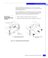
Servicing and Upgrading a DPE 3 Latch 3. Remove the power-supply module, as shown in Figures 3-29 and 3-30. A. With your thumb, push the latch up and then right as far as possible. You may need to brace your hand against the supply module's handle. B. Grasp the handle with one hand, and gently pull the module from the enclosure, supporting it with your other hand. Figure 3-29 Removing the Top Power-Supply Module 3-40 EMC Fibre Channel Disk-Array Processor Enclosure (DPE) Hardware Reference
-
 1
1 -
2
-
3
-
4
-
5
-
6
-
7
-
8
-
9
-
10
-
11
-
12
-
13
-
14
-
15
-
16
-
17
-
18
-
19
-
20
-
21
-
22
-
23
-
24
-
25
-
26
-
27
-
28
-
29
-
30
-
31
-
32
-
33
-
34
-
35
-
36
-
37
-
38
-
39
-
40
-
41
-
42
-
43
-
44
-
45
-
46
-
47
-
48
-
49
-
50
-
51
-
52
-
53
-
54
-
55
-
56
-
57
-
58
-
59
-
60
-
61
-
62
-
63
-
64
-
65
-
66
-
67
-
68
-
69
-
70
-
71
-
72
-
73
-
74
-
75
-
76
-
77
-
78
-
79
-
80
-
81
-
82
-
 83
83 -
 84
84 -
 85
85 -
 86
86 -
 87
87 -
 88
88 -
 89
89 -
 90
90 -
 91
91 -
 92
92 -
 93
93 -
94
-
95
-
96
-
97
-
98
-
99
-
100
-
101
-
102
-
103
-
104
-
105
-
106
-
107
-
108
-
109
-
110
 |
 |

3
3-40
EMC Fibre Channel Disk-Array Processor Enclosure (DPE) Hardware Reference
Servicing and Upgrading a DPE
3.
Remove the power-supply module, as shown in Figures 3-29 and
3-30.
Figure 3-29
Removing the Top Power-Supply Module
Latch
A.
With your thumb, push the latch up
and then right as far as possible.
B.
Grasp the handle with one hand, and
gently pull the module from the enclosure,
supporting it with your other hand.
You may need to brace your hand
against the supply module's handle.