Dell FC4500 Reference Guide - Page 24
Disk Modules, Disk Drives, FC-AL Private Loop Direct Attach PLDA profile
 |
View all Dell FC4500 manuals
Add to My Manuals
Save this manual to your list of manuals |
Page 24 highlights
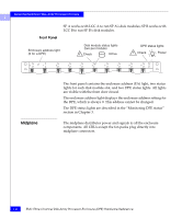
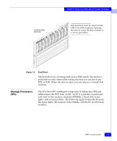
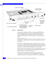
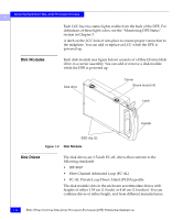
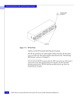
About the Rackmount Disk-Array Processor Enclosure 1 Each LCC has two status lights visible from the back of the DPE. For definitions of these light colors, see the "Monitoring DPE Status" section in Chapter 3. A latch on the LCC locks it into place to ensure proper connection to the midplane. You can add or replace an LCC while the DPE is powered up. Disk Modules Each disk module (see figure below) consists of a Fibre Channel disk drive in a carrier assembly. You can add or remove a disk module while the DPE is powered up. Disk drive Carrier Shock mount (4) Latch Handle ESD clip (2) Figure 1-9 Disk Module Disk Drives The disk drives are 3.5-inch FC-AL drives that conform to the following standards: • SFF-8067 • Fibre Channel Arbitrated Loop (FC-AL) • FC-AL Private Loop Direct Attach (PLDA) profile The disk module slots in the enclosure accommodate drives with heights of either 2.54 cm (1.0 inch) or 4.06 cm (1.6 inches). You can combine drives of either height, and from different manufacturers, 1-12 EMC Fibre Channel Disk-Array Processor Enclosure (DPE) Hardware Reference
-
 1
1 -
2
-
3
-
4
-
5
-
6
-
7
-
8
-
9
-
10
-
11
-
12
-
13
-
14
-
15
-
16
-
17
-
18
-
 19
19 -
 20
20 -
 21
21 -
 22
22 -
 23
23 -
 24
24 -
 25
25 -
 26
26 -
 27
27 -
 28
28 -
 29
29 -
30
-
31
-
32
-
33
-
34
-
35
-
36
-
37
-
38
-
39
-
40
-
41
-
42
-
43
-
44
-
45
-
46
-
47
-
48
-
49
-
50
-
51
-
52
-
53
-
54
-
55
-
56
-
57
-
58
-
59
-
60
-
61
-
62
-
63
-
64
-
65
-
66
-
67
-
68
-
69
-
70
-
71
-
72
-
73
-
74
-
75
-
76
-
77
-
78
-
79
-
80
-
81
-
82
-
83
-
84
-
85
-
86
-
87
-
88
-
89
-
90
-
91
-
92
-
93
-
94
-
95
-
96
-
97
-
98
-
99
-
100
-
101
-
102
-
103
-
104
-
105
-
106
-
107
-
108
-
109
-
110
 |
 |
