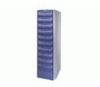
Dell FC4500 Reference Guide - Page 6

Servicing and Upgrading a DPE, Appendix A, Technical Specifications and Operating Limits - array

Page 6 highlights

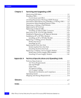
Contents Chapter 3 Servicing and Upgrading a DPE Monitoring DPE Status 3-1 Handling CRUs 3-4 Power Issues and CRUs 3-4 Avoiding Electrostatic Discharge (ESD) Damage 3-6 Precautions When Removing, Installing, or Storing CRUs ........3-7 Precautions When Handling Optical Cables 3-8 Replacing or Adding a Disk Module 3-9 Replacing the SP Fan Pack 3-14 Replacing an Optical GBIC 3-17 Installing an Optical GBIC Connector 3-19 Removing an SP or an SP Filler Module 3-21 Installing or Replacing an SP Memory Module 3-24 Installing an SP or SP Filler Module 3-26 Installing an SP or SP Filler Module 3-27 Replacing or Adding an LCC Module 3-30 Removing an LCC 3-30 Installing an LCC 3-32 Replacing the Drive Fan Pack 3-34 Removing the Drive Fan Pack 3-35 Installing the Drive Fan Pack 3-35 Replacing or Adding a Power-Supply Module 3-36 Removing a Power-Supply Filler Module 3-37 Installing a Power-Supply Module 3-41 Appendix A Technical Specifications and Operating Limits Technical Specifications A-1 AC Power Requirements A-1 Size and Weight A-2 Drive Type A-3 SP Optical Cabling A-3 LCC Copper Cabling A-3 Standards Certification and Compliance A-3 Operating Limits A-5 Shipping and Storage Requirements A-6 Glossary ...g-1 Index ...i-1 vi EMC Fibre Channel Disk-Array Processor Enclosure (DPE) Hardware Reference

  • 1
  • 2
  • 3
  • 4
  • 5
  • 6
  • 7
  • 8
  • 9
  • 10
  • 11
  • 12
  • 13
  • 14
  • 15
  • 16
  • 17
  • 18
  • 19
  • 20
  • 21
  • 22
  • 23
  • 24
  • 25
  • 26
  • 27
  • 28
  • 29
  • 30
  • 31
  • 32
  • 33
  • 34
  • 35
  • 36
  • 37
  • 38
  • 39
  • 40
  • 41
  • 42
  • 43
  • 44
  • 45
  • 46
  • 47
  • 48
  • 49
  • 50
  • 51
  • 52
  • 53
  • 54
  • 55
  • 56
  • 57
  • 58
  • 59
  • 60
  • 61
  • 62
  • 63
  • 64
  • 65
  • 66
  • 67
  • 68
  • 69
  • 70
  • 71
  • 72
  • 73
  • 74
  • 75
  • 76
  • 77
  • 78
  • 79
  • 80
  • 81
  • 82
  • 83
  • 84
  • 85
  • 86
  • 87
  • 88
  • 89
  • 90
  • 91
  • 92
  • 93
  • 94
  • 95
  • 96
  • 97
  • 98
  • 99
  • 100
  • 101
  • 102
  • 103
  • 104
  • 105
  • 106
  • 107
  • 108
  • 109
  • 110

EMC Fibre Channel Disk-Array Processor Enclosure (DPE) Hardware Reference
vi
Contents
Chapter 3
Servicing and Upgrading a DPE
Monitoring DPE Status
....................................................................
3-1
Handling CRUs
.................................................................................
3-4
Power Issues and CRUs
............................................................
3-4
Avoiding Electrostatic Discharge (ESD) Damage
........................
3-6
Precautions When Removing, Installing, or Storing CRUs
........
3-7
Precautions When Handling Optical Cables
................................
3-8
Replacing or Adding a Disk Module
.............................................
3-9
Replacing the SP Fan Pack
............................................................
3-14
Replacing an Optical GBIC
............................................................
3-17
Installing an Optical GBIC Connector
..................................
3-19
Removing an SP or an SP Filler Module
.....................................
3-21
Installing or Replacing an SP Memory Module
.........................
3-24
Installing an SP or SP Filler Module
............................................
3-26
Installing an SP or SP Filler Module
.....................................
3-27
Replacing or Adding an LCC Module
.........................................
3-30
Removing an LCC
...................................................................
3-30
Installing an LCC
.....................................................................
3-32
Replacing the Drive Fan Pack
.......................................................
3-34
Removing the Drive Fan Pack
...............................................
3-35
Installing the Drive Fan Pack
.................................................
3-35
Replacing or Adding a Power-Supply Module
..........................
3-36
Removing a Power-Supply Filler Module
...........................
3-37
Installing a Power-Supply Module
.......................................
3-41
Appendix A
Technical Specifications and Operating Limits
Technical Specifications
.................................................................
A-1
AC Power Requirements
.........................................................
A-1
Size and Weight
........................................................................
A-2
Drive Type
.................................................................................
A-3
SP Optical Cabling
....................................................................
A-3
LCC Copper Cabling
................................................................
A-3
Standards Certification and Compliance
..............................
A-3
Operating Limits
.............................................................................
A-5
Shipping and Storage Requirements
...........................................
A-6
Glossary
.........................................................................................................................
g-1
Index
.................................................................................................................................
i-1