Dell FC4500 Reference Guide - Page 8

Turning off a Supply's Power and Unplugging the AC Line Cord - sps

Page 8 highlights

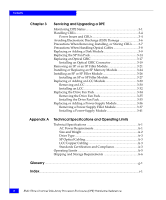
Figures 3-6 Closing and Locking the Front Door 3-13 3-7 Removing the SP Fan Pack Cover 3-14 3-8 Removing the SP Fan Pack 3-15 3-9 Installing the Replacement SP Fan Pack 3-16 3-10 Installing the SP Fan Pack Cover 3-17 3-11 Removing an Optical Cable from an SP 3-18 3-12 Removing an Optical GBIC Connector from an SP 3-19 3-13 Installing an Optical GBIC Connector on an SP 3-20 3-14 Installing an Optical Cable on an SP 3-21 3-15 Removing an SP or Filler Module 3-23 3-16 Removing the Memory Module from the SP 3-25 3-17 Installing the Memory Module on the SP 3-26 3-18 Setting the SP Address ID 3-28 3-19 Installing an SP or SP Filler Module 3-29 3-20 Removing an LCC Filler Module 3-31 3-21 Removing a Copper Cable from an LCC 3-31 3-22 Installing an LCC Module 3-33 3-23 Reconnecting a Copper Cable to an Expansion LCC 3-34 3-24 Removing the Drive Fan Pack 3-35 3-25 Installing the Drive Fan Pack 3-36 3-26 Removing the Bottom Filler Module 3-37 3-27 Removing the Top Filler Module 3-38 3-28 Turning off a Supply's Power and Unplugging the AC Line Cord ..... 3-39 3-29 Removing the Top Power-Supply Module 3-40 3-30 Removing the Bottom Power-Supply Module 3-41 3-31 Installing the Bottom Power Supply 3-42 3-32 Installing the Top Power Supply 3-43 3-33 Plugging in the AC Line Cord and Turning on Power 3-44 viii EMC Fibre Channel Disk-Array Processor Enclosure (DPE) Hardware Reference

  • 1
  • 2
  • 3
  • 4
  • 5
  • 6
  • 7
  • 8
  • 9
  • 10
  • 11
  • 12
  • 13
  • 14
  • 15
  • 16
  • 17
  • 18
  • 19
  • 20
  • 21
  • 22
  • 23
  • 24
  • 25
  • 26
  • 27
  • 28
  • 29
  • 30
  • 31
  • 32
  • 33
  • 34
  • 35
  • 36
  • 37
  • 38
  • 39
  • 40
  • 41
  • 42
  • 43
  • 44
  • 45
  • 46
  • 47
  • 48
  • 49
  • 50
  • 51
  • 52
  • 53
  • 54
  • 55
  • 56
  • 57
  • 58
  • 59
  • 60
  • 61
  • 62
  • 63
  • 64
  • 65
  • 66
  • 67
  • 68
  • 69
  • 70
  • 71
  • 72
  • 73
  • 74
  • 75
  • 76
  • 77
  • 78
  • 79
  • 80
  • 81
  • 82
  • 83
  • 84
  • 85
  • 86
  • 87
  • 88
  • 89
  • 90
  • 91
  • 92
  • 93
  • 94
  • 95
  • 96
  • 97
  • 98
  • 99
  • 100
  • 101
  • 102
  • 103
  • 104
  • 105
  • 106
  • 107
  • 108
  • 109
  • 110

viii
EMC Fibre Channel Disk-Array Processor Enclosure (DPE) Hardware Reference
Figures
3-6
Closing and Locking the Front Door
........................................................
3-13
3-7
Removing the SP Fan Pack Cover
............................................................
3-14
3-8
Removing the SP Fan Pack
........................................................................
3-15
3-9
Installing the Replacement SP Fan Pack
..................................................
3-16
3-10
Installing the SP Fan Pack Cover
..............................................................
3-17
3-11
Removing an Optical Cable from an SP
..................................................
3-18
3-12
Removing an Optical GBIC Connector from an SP
...............................
3-19
3-13
Installing an Optical GBIC Connector on an SP
.....................................
3-20
3-14
Installing an Optical Cable on an SP
........................................................
3-21
3-15
Removing an SP or Filler Module
.............................................................
3-23
3-16
Removing the Memory Module from the SP
..........................................
3-25
3-17
Installing the Memory Module on the SP
................................................
3-26
3-18
Setting the SP Address ID
..........................................................................
3-28
3-19
Installing an SP or SP Filler Module
.........................................................
3-29
3-20
Removing an LCC Filler Module
..............................................................
3-31
3-21
Removing a Copper Cable from an LCC
.................................................
3-31
3-22
Installing an LCC Module
..........................................................................
3-33
3-23
Reconnecting a Copper Cable to an Expansion LCC
.............................
3-34
3-24
Removing the Drive Fan Pack
...................................................................
3-35
3-25
Installing the Drive Fan Pack
....................................................................
3-36
3-26
Removing the Bottom Filler Module
........................................................
3-37
3-27
Removing the Top Filler Module
..............................................................
3-38
3-28
Turning off a Supply’s Power and Unplugging the AC Line Cord
.....
3-39
3-29
Removing the Top Power-Supply Module
.............................................
3-40
3-30
Removing the Bottom Power-Supply Module
.......................................
3-41
3-31
Installing the Bottom Power Supply
........................................................
3-42
3-32
Installing the Top Power Supply
..............................................................
3-43
3-33
Plugging in the AC Line Cord and Turning on Power
.........................
3-44