Dell FC4500 Reference Guide - Page 25
Drive Carrier, Power Supplies, switch. Each supply supports a fully con d DPE and shares load
 |
View all Dell FC4500 manuals
Add to My Manuals
Save this manual to your list of manuals |
Page 25 highlights
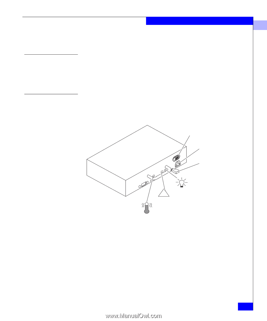
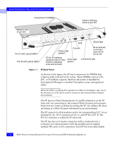
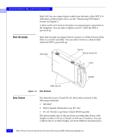
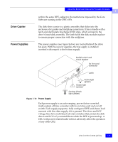
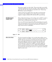
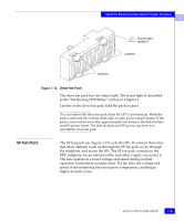
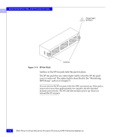
Drive Carrier Power Supplies About the Rackmount Disk-Array Processor Enclosure 1 within the same DPE, subject to the restrictions imposed by the Core Software running in the DPE's SPs. The disk-drive carrier is a plastic assembly that slides into the enclosure slot guides and midplane connectors. It has a handle with a latch and electrostatic discharge (ESD) clips, which connect to the drive's head-disk assembly. The latch holds the disk module in place to ensure proper connection with the midplane. The power supplies (see figure below) are located behind the drive fan pack. With two power supplies, the top supply is installed inverted with respect to the bottom supply. On/Off switch and circuit breaker Ac line cord connector Latch Active light (green) ! Check light (amber) Cooling Check light (amber) Figure 1-10 Power Supply Each power supply is an auto-ranging, power-factor-corrected, multi-output, off-line converter with its own line cord and on/off switch. Each supply supports a fully configured DPE and shares load currents with the other supply, if it is present. The drive and LCC voltage lines have individual soft-start switches that protect the disk drives and LCCs if you install them while the DPE is powered up. A CRU with power-related faults will not adversely affect the operation of any other CRU. Link Control Cards (LCCs) 1-13
-
 1
1 -
2
-
3
-
4
-
5
-
6
-
7
-
8
-
9
-
10
-
11
-
12
-
13
-
14
-
15
-
16
-
17
-
18
-
19
-
 20
20 -
 21
21 -
 22
22 -
 23
23 -
 24
24 -
 25
25 -
 26
26 -
 27
27 -
 28
28 -
 29
29 -
 30
30 -
31
-
32
-
33
-
34
-
35
-
36
-
37
-
38
-
39
-
40
-
41
-
42
-
43
-
44
-
45
-
46
-
47
-
48
-
49
-
50
-
51
-
52
-
53
-
54
-
55
-
56
-
57
-
58
-
59
-
60
-
61
-
62
-
63
-
64
-
65
-
66
-
67
-
68
-
69
-
70
-
71
-
72
-
73
-
74
-
75
-
76
-
77
-
78
-
79
-
80
-
81
-
82
-
83
-
84
-
85
-
86
-
87
-
88
-
89
-
90
-
91
-
92
-
93
-
94
-
95
-
96
-
97
-
98
-
99
-
100
-
101
-
102
-
103
-
104
-
105
-
106
-
107
-
108
-
109
-
110
 |
 |