Dell FC4500 Reference Guide - Page 45
If this DAE, DAE Installation Manual
 |
View all Dell FC4500 manuals
Add to My Manuals
Save this manual to your list of manuals |
Page 45 highlights
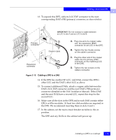
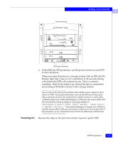
Installing a Rackmount DPE 2 13. To expand this DPE, cable its LCC EXP connector to the next corresponding DAE's PRI (primary) connector, as shown below. IMPORTANT: Do not connect a cable between an LCC in slot A and an LCC in slot B. Primary connector Copper cable A. Plug one end of a copper cable into the expansion (EXP) connector on an LCC in the DPE. B. Tighten the two thumb screws on the cable's connector. Expansion connector C. Plug the other end of the copper cable into the primary (PRI) connector on the matching LCC in the DAE. D. Tighten the two screws on the cable's connector. Figure 2-10 Cabling a DPE to a DAE 14. If the DPE has another SP, LCC, and DAE, connect the DPE's other LCC and the DAE's other LCC as above. 15. To connect additional DAEs, attach a copper cable between the DAE's LCC EXP connector and the next DAE's PRI (primary) connector (detailed in the DAE Installation Manual). If this DAE and the next DAE have a second LCC, repeat this step for the second LCC. 16. Make sure all the slots in the DPE and in each DAE contain either CRUs or filler modules. At least two disk modules are required in the DPE. We recommend inserting them in slots 0 and 1. 17. In the cabinet, set the main circuit breaker switches to the on position. The DPE and any DAEs in the cabinet will power up. Installing a DPE in a Cabinet 2-15
-
 1
1 -
2
-
3
-
4
-
5
-
6
-
7
-
8
-
9
-
10
-
11
-
12
-
13
-
14
-
15
-
16
-
17
-
18
-
19
-
20
-
21
-
22
-
23
-
24
-
25
-
26
-
27
-
28
-
29
-
30
-
31
-
32
-
33
-
34
-
35
-
36
-
37
-
38
-
39
-
 40
40 -
 41
41 -
 42
42 -
 43
43 -
 44
44 -
 45
45 -
 46
46 -
 47
47 -
 48
48 -
 49
49 -
 50
50 -
51
-
52
-
53
-
54
-
55
-
56
-
57
-
58
-
59
-
60
-
61
-
62
-
63
-
64
-
65
-
66
-
67
-
68
-
69
-
70
-
71
-
72
-
73
-
74
-
75
-
76
-
77
-
78
-
79
-
80
-
81
-
82
-
83
-
84
-
85
-
86
-
87
-
88
-
89
-
90
-
91
-
92
-
93
-
94
-
95
-
96
-
97
-
98
-
99
-
100
-
101
-
102
-
103
-
104
-
105
-
106
-
107
-
108
-
109
-
110
 |
 |
