Dell FC4500 Reference Guide - Page 73
Installing an SP, Memory Module, Place the SP and the memory module DIMM on a static-free
 |
View all Dell FC4500 manuals
Add to My Manuals
Save this manual to your list of manuals |
Page 73 highlights
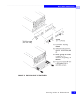
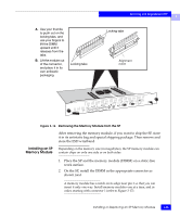
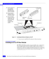
A. Use your thumbs to push out on the locking tabs, and use your fingers to lift the DIMM upward until it releases from the tabs. B. Lift the module out of the connector, and place it in its own antistatic packaging. Locking tabs Servicing and Upgrading a DPE 3 Locking tabs Alignment notch Figure 3-16 Removing the Memory Module from the SP After removing the memory module, if you want to ship the SP, store it in its antistatic bag and special shipping package. Then remove and store the ESD wristband. Installing an SP Memory Module Depending on the memory size (in megabytes), the SP memory module can contain chips on only one side or on both sides. 1. Place the SP and the memory module (DIMM) on a static-free work surface. 2. On the SP, install the DIMM in the appropriate connector as shown next. A memory module has a notch on its edge near pin 1 so that you can insert it only one way. Install memory modules one at a time, and in order, starting with connector 1 (refer to Figure 3-17). Installing or Replacing an SP Memory Module 3-25
-
 1
1 -
2
-
3
-
4
-
5
-
6
-
7
-
8
-
9
-
10
-
11
-
12
-
13
-
14
-
15
-
16
-
17
-
18
-
19
-
20
-
21
-
22
-
23
-
24
-
25
-
26
-
27
-
28
-
29
-
30
-
31
-
32
-
33
-
34
-
35
-
36
-
37
-
38
-
39
-
40
-
41
-
42
-
43
-
44
-
45
-
46
-
47
-
48
-
49
-
50
-
51
-
52
-
53
-
54
-
55
-
56
-
57
-
58
-
59
-
60
-
61
-
62
-
63
-
64
-
65
-
66
-
67
-
 68
68 -
 69
69 -
 70
70 -
 71
71 -
 72
72 -
 73
73 -
 74
74 -
 75
75 -
 76
76 -
 77
77 -
 78
78 -
79
-
80
-
81
-
82
-
83
-
84
-
85
-
86
-
87
-
88
-
89
-
90
-
91
-
92
-
93
-
94
-
95
-
96
-
97
-
98
-
99
-
100
-
101
-
102
-
103
-
104
-
105
-
106
-
107
-
108
-
109
-
110
 |
 |
