Dell Latitude E6400 XFR Service Manual - Page 22
Bottom Access Panel - keyboard com
 |
View all Dell Latitude E6400 XFR manuals
Add to My Manuals
Save this manual to your list of manuals |
Page 22 highlights
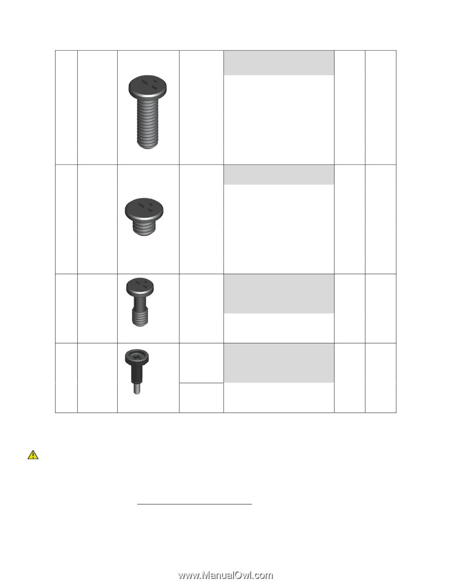
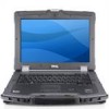
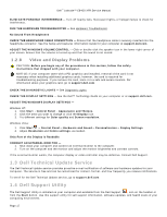
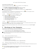
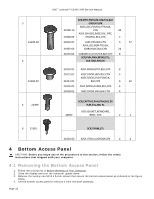
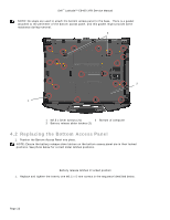
3 21106‐02 4 21106‐03 5 21399 Dell™ Latitude™ E6400 XFR Service Manual SCR,PHH,PNH,M2.5X8,STL,BLK OXD,NYLOK BASE,DSC,PCMCIA,FPR,BLK, 21900‐10 CYN 20 ASSY,CHASSIS,BASE,DSC, PRC, 21000‐03 PCMCIA, BLK,CYN 2 21030‐01 21902‐03 ASSY,HDL,BLK,CYN ASSY,LCD,NON TOUCH, CMRA+MIC,BLK,CYN 3 57 24 21051‐01 SUBASSY,LCD OUTER,BLK,CYN 8 SCR,PHH,PNH,M3X3,STL, BLK OXD,NYLOK 21010‐01 ASSY,DOOR,BTRY,BLK,CYN 8 21012‐01 ASSY,DOOR,HDD,BLK,CYN 4 ASSY,DOOR,DVD,PCMCIA, 21014‐01 BLK,CYN 6 26 21016‐01 ASSY,DOOR,AUDIO,BLK,CYN 4 21018‐01 ASSY,DOOR,VGA,BLK,CYN 4 SCR,CAPTIVE,PHH,PNH,M2.5X 9.85,STL,NKL PL ASSY,GASKET,KEYBOARD, 40057 BRKT, CYN 2 2 6 21381 SCR,THRM,STL 21034‐00 ASSY,HTSK,CU,GROM,CYN 4 4 4 Bottom Access Panel CAUTION: Before you begin any of the procedures in this section, follow the safety instructions that shipped with your computer. 4.1 Removing the Bottom Access Panel 1. Follow the procedures in Before Working on Your Computer. 2. Close the display and turn the computer upside down. 3. Remove the twenty-one M2.5 x 5-mm screws that secure the bottom access panel as indicated in the figure below. 4. Lift the bottom access panel to remove it from the base assembly. Page 22
-
 1
1 -
2
-
3
-
4
-
5
-
6
-
7
-
8
-
9
-
10
-
11
-
12
-
13
-
14
-
15
-
16
-
 17
17 -
 18
18 -
 19
19 -
 20
20 -
 21
21 -
 22
22 -
 23
23 -
 24
24 -
 25
25 -
 26
26 -
 27
27 -
28
-
29
-
30
-
31
-
32
-
33
-
34
-
35
-
36
-
37
-
38
-
39
-
40
-
41
-
42
-
43
-
44
-
45
-
46
-
47
-
48
-
49
-
50
-
51
-
52
-
53
-
54
-
55
-
56
-
57
-
58
-
59
-
60
-
61
-
62
-
63
-
64
-
65
-
66
-
67
-
68
-
69
-
70
-
71
-
72
-
73
-
74
 |
 |