Dell Latitude E6400 XFR Service Manual - Page 40
Palm Rest Overlay
 |
View all Dell Latitude E6400 XFR manuals
Add to My Manuals
Save this manual to your list of manuals |
Page 40 highlights
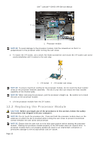
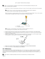
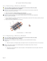
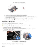
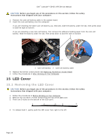
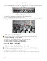
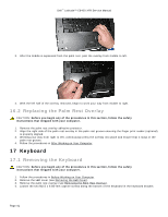
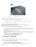
Dell™ Latitude™ E6400 XFR Service Manual 5. While still applying pressure to the left, use a plastic scribe to pry up on the left corner of the LED cover. 2 3 1 1 Scribe 2 LED cover 3 M2.5 x 5-mm screw (2) 6. Hooks 2and 3 are released individually by using a left and upward motion. 7. Hook 4 is released by using a right and upward motion. 8. Hook 5 is released by placing light left pressure on the assembly, then rotating the back edge slightly while prying with the plastic scribe. 15.2 Replacing the LED Cover CAUTION: Before you begin any of the procedures in this section, follow the safety instructions that shipped with your computer. 1. Working at an angle, snap the LED cover into place one hook at a time. 2. Add the two M2.5 x 5-mm screws to secure the LED cover. 3. Follow the procedures in After Working on Your Computer. 16 Palm Rest Overlay 16.1 Removing the Palm Rest Overlay CAUTION: Before you begin any of the procedures in this section, follow the safety instructions that shipped with your computer. 1. Follow the procedures in Before Working on Your Computer. 2. Starting from the middle of the palm rest overlay, carefully peel the overlay away from the base. Page 40
-
 1
1 -
2
-
3
-
4
-
5
-
6
-
7
-
8
-
9
-
10
-
11
-
12
-
13
-
14
-
15
-
16
-
17
-
18
-
19
-
20
-
21
-
22
-
23
-
24
-
25
-
26
-
27
-
28
-
29
-
30
-
31
-
32
-
33
-
34
-
 35
35 -
 36
36 -
 37
37 -
 38
38 -
 39
39 -
 40
40 -
 41
41 -
 42
42 -
 43
43 -
 44
44 -
 45
45 -
46
-
47
-
48
-
49
-
50
-
51
-
52
-
53
-
54
-
55
-
56
-
57
-
58
-
59
-
60
-
61
-
62
-
63
-
64
-
65
-
66
-
67
-
68
-
69
-
70
-
71
-
72
-
73
-
74
 |
 |
