Dell Latitude E6400 XFR Service Manual - Page 24
WLAN/WiMax Card
 |
View all Dell Latitude E6400 XFR manuals
Add to My Manuals
Save this manual to your list of manuals |
Page 24 highlights
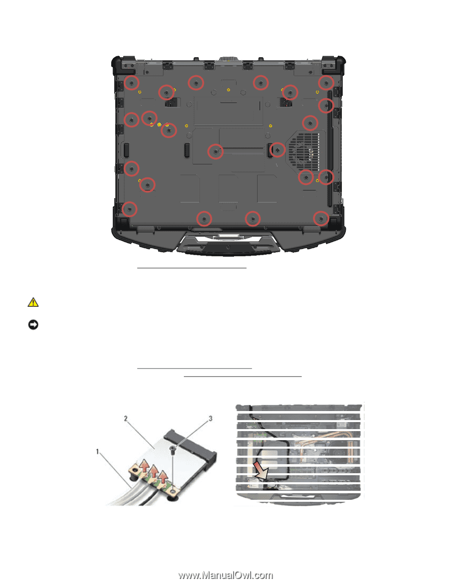
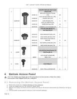
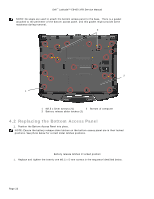
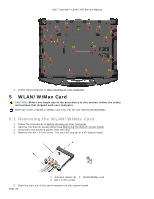
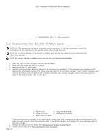
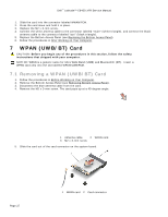
Dell™ Latitude™ E6400 XFR Service Manual 4 20 21 5 1 2 6 3 7 14 8 19 17 18 16 15 13 12 11 9 10 2. Follow the procedures in After Working on Your Computer. 5 WLAN/WiMax Card CAUTION: Before you begin any of the procedures in this section, follow the safety instructions that shipped with your computer. NOTICE: Insert a WLAN or WiMax card only into the slot labeled WLAN/WiMax. 5.1 Removing the WLAN/WiMax Card 1. Follow the procedures in Before Working on Your Computer. 2. Remove the Bottom Access Panel (see Removing the Bottom Access Panel). 3. Disconnect the antenna cables from the card. 4. Remove the M2 x 3-mm screw. The card will pop up at a 45-degree angle. 1 Antenna cables (3) 2 WLAN/WiMax card 3 M2 x 3-mm screw 5. Slide the card out of the card connector on the system board. Page 24
-
 1
1 -
2
-
3
-
4
-
5
-
6
-
7
-
8
-
9
-
10
-
11
-
12
-
13
-
14
-
15
-
16
-
17
-
18
-
 19
19 -
 20
20 -
 21
21 -
 22
22 -
 23
23 -
 24
24 -
 25
25 -
 26
26 -
 27
27 -
 28
28 -
 29
29 -
30
-
31
-
32
-
33
-
34
-
35
-
36
-
37
-
38
-
39
-
40
-
41
-
42
-
43
-
44
-
45
-
46
-
47
-
48
-
49
-
50
-
51
-
52
-
53
-
54
-
55
-
56
-
57
-
58
-
59
-
60
-
61
-
62
-
63
-
64
-
65
-
66
-
67
-
68
-
69
-
70
-
71
-
72
-
73
-
74
 |
 |