Dell Latitude E6400 XFR Service Manual - Page 50
Smartcard Assembly - replacement keyboard
 |
View all Dell Latitude E6400 XFR manuals
Add to My Manuals
Save this manual to your list of manuals |
Page 50 highlights
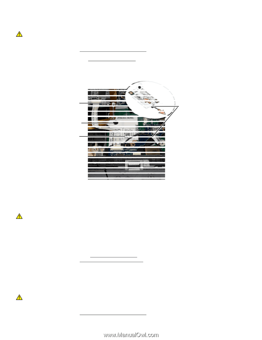
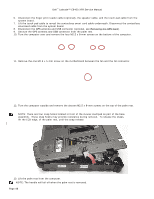
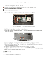
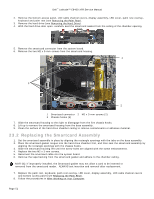
Dell™ Latitude™ E6400 XFR Service Manual CAUTION: Before you begin any of the procedures in this section, follow the safety instructions that shipped with your computer. 1. Follow the procedures in Before Working on Your Computer. 2. Remove the bottom access panel, LCD cable channel covers, display assembly, led cover, palm rest overlay, keyboard and palm rest (see Removing the Palm Rest). 3. Remove the M2 x 3-mm screw from the modem. 4. Use the pull tab to remove the modem from the I/O card. 5. Disconnect the modem cable from the modem. 1 2 4 3 1 M2 x 3-mm screw 2 Modem cable 3 Modem 4 Pull tab 22.2 Replacing the Modem CAUTION: Before you begin any of the procedures in this section, follow the safety instructions that shipped with your computer. 1. Connect the modem cable to the modem. 2. Use the screw hole on the modem to align it with the connector on the I/O card. 3. Press the area on the modem marked "Press Here" to connect the modem to the I/O card. 4. Replace the M2 x 3-mm screw to secure the modem to the I/O card. 5. Replace the palm rest, keyboard, palm rest overlay, LED cover, display assembly, LCD cable channel covers and bottom access panel (see Replacing the Palm Rest). 6. Follow the procedures in After Working on Your Computer. 23 Smartcard Assembly 23.1 Removing the Smartcard Assembly CAUTION: Before you begin any of the procedures in this section, follow the safety instructions that shipped with your computer. 1. Follow the procedures in Before Working on Your Computer. Page 50
-
 1
1 -
2
-
3
-
4
-
5
-
6
-
7
-
8
-
9
-
10
-
11
-
12
-
13
-
14
-
15
-
16
-
17
-
18
-
19
-
20
-
21
-
22
-
23
-
24
-
25
-
26
-
27
-
28
-
29
-
30
-
31
-
32
-
33
-
34
-
35
-
36
-
37
-
38
-
39
-
40
-
41
-
42
-
43
-
44
-
 45
45 -
 46
46 -
 47
47 -
 48
48 -
 49
49 -
 50
50 -
 51
51 -
 52
52 -
 53
53 -
 54
54 -
 55
55 -
56
-
57
-
58
-
59
-
60
-
61
-
62
-
63
-
64
-
65
-
66
-
67
-
68
-
69
-
70
-
71
-
72
-
73
-
74
 |
 |