Dell Latitude E6400 XFR Service Manual - Page 66
Doors
 |
View all Dell Latitude E6400 XFR manuals
Add to My Manuals
Save this manual to your list of manuals |
Page 66 highlights
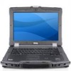
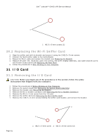
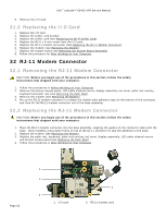
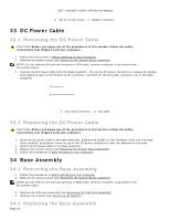
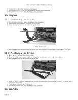
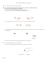
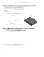
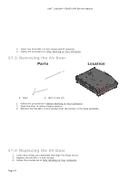
Dell™ Latitude™ E6400 XFR Service Manual NOTICE: Image above has palm rest removed to show tab socket close-up. During installation, verify handle pinions are inserted into the tab sockets properly during reassembly. 2. Replace the four M2.5 x 8-mm bottom retaining screws. 3. Replace the six M2.5 x 8-mm palm rest retaining screws. 4. Follow the procedures in After Working on Your Computer. 37 Doors 37.1 Removing Media Bay Door Parts Location 1 2 1 Media bay door 2 M3 x 3 mm screws (3) CAUTION: Before you begin any of the procedures in this section, follow the safety instructions that shipped with your computer. 1. Follow the procedures in Before Working on Your Computer. 2. Open the door to relieve hinge pressure. 3. Remove the three M3 x 3-mm screws from the bottom of the base assembly 37.2 Replacing Media Bay Door 1. Insert door hinge onto assembly and align the hinge divots. Page 66
-
 1
1 -
2
-
3
-
4
-
5
-
6
-
7
-
8
-
9
-
10
-
11
-
12
-
13
-
14
-
15
-
16
-
17
-
18
-
19
-
20
-
21
-
22
-
23
-
24
-
25
-
26
-
27
-
28
-
29
-
30
-
31
-
32
-
33
-
34
-
35
-
36
-
37
-
38
-
39
-
40
-
41
-
42
-
43
-
44
-
45
-
46
-
47
-
48
-
49
-
50
-
51
-
52
-
53
-
54
-
55
-
56
-
57
-
58
-
59
-
60
-
 61
61 -
 62
62 -
 63
63 -
 64
64 -
 65
65 -
 66
66 -
 67
67 -
 68
68 -
 69
69 -
 70
70 -
 71
71 -
72
-
73
-
74
 |
 |