Dell Latitude E6400 XFR Service Manual - Page 45
Latitude™ E6400 XFR Service Manual - motherboard
 |
View all Dell Latitude E6400 XFR manuals
Add to My Manuals
Save this manual to your list of manuals |
Page 45 highlights
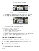
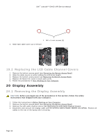
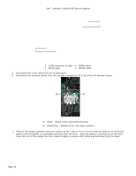
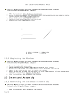
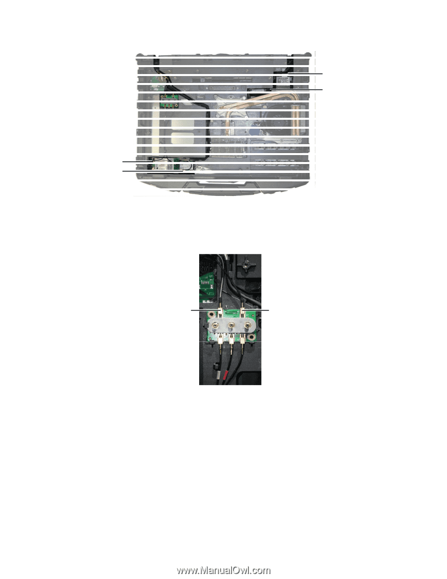
Dell™ Latitude™ E6400 XFR Service Manual 2 1 4 3 1 LVDS connector & cable 2 WPAN cable 3 WLAN cable 4 WWAN cable 5. Disconnect the LVDS cable from the motherboard. 6. Disconnect the antenna cables from the top side connectors (J4 & J5) of the RF Passthru board. J5 J4 J4 Black - WLAN (from LCD panel antenna) J5 Black/Grey - WWAN (from LCD panel antenna 7. Remove the display gaskets using your plastic scribe. Use an in-out motion altering sides on an individual gasket until the gasket is completely removed from the base. Once the gasket is pushed out of the base, route the rest of the cables thru the chassis bridge to remove LCD cables and antennas from the base. Page 45
-
 1
1 -
2
-
3
-
4
-
5
-
6
-
7
-
8
-
9
-
10
-
11
-
12
-
13
-
14
-
15
-
16
-
17
-
18
-
19
-
20
-
21
-
22
-
23
-
24
-
25
-
26
-
27
-
28
-
29
-
30
-
31
-
32
-
33
-
34
-
35
-
36
-
37
-
38
-
39
-
 40
40 -
 41
41 -
 42
42 -
 43
43 -
 44
44 -
 45
45 -
 46
46 -
 47
47 -
 48
48 -
 49
49 -
 50
50 -
51
-
52
-
53
-
54
-
55
-
56
-
57
-
58
-
59
-
60
-
61
-
62
-
63
-
64
-
65
-
66
-
67
-
68
-
69
-
70
-
71
-
72
-
73
-
74
 |
 |
Dell
™
Latitude™ E6400 XFR Service Manual
Page 45
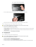
1
LVDS connector & cable
2
WPAN cable
3 WLAN cable
4
WWAN cable
5.
Disconnect the LVDS cable from the motherboard.
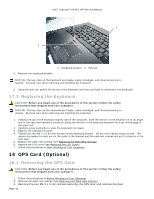
6.
Disconnect the antenna cables from the top side connectors (J4 & J5) of the RF Passthru board.
J4
Black – WLAN (from LCD panel antenna)
J5
Black/Grey – WWAN (from LCD panel antenna
7.
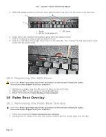
Remove the display gaskets using your plastic scribe.
Use an in-out motion altering sides on an individual
gasket until the gasket is completely removed from the base.
Once the gasket is pushed out of the base,
route the rest of the cables thru the chassis bridge to remove LCD cables and antennas from the base.
2
1
3
4
J5
J4