Dell PowerConnect Brocade M6505 Brocade 7.1.0 Access Gateway Administrator's G - Page 36
Port mapping, Default port mapping
 |
View all Dell PowerConnect Brocade M6505 manuals
Add to My Manuals
Save this manual to your list of manuals |
Page 36 highlights
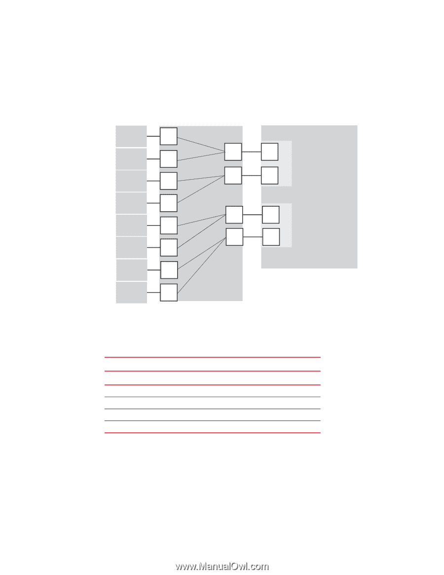
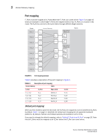
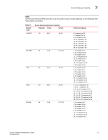
2 Access Gateway mapping Port mapping F_Ports must be mapped to N_Ports before the F_Ports can come online. Figure 5 on page 16 shows an example in which eight F_Ports are mapped evenly to four N_Ports on a switch in AG mode. The N_Ports connect to the same fabric through different Edge switches. Hosts Host_1 Host_2 Host_3 Host_4 Host_5 Host_6 Access Gateway F_1 N_1 F_2 N_2 F_3 F_4 N_3 F_5 N_4 F_6 Edge Switch (Switch_A) F_A1 NPIV enabled F_A2 NPIV enabled Edge Switch (Switch_B) F_B1 NPIV enabled F_B2 NPIV enabled Fabric Host_7 F_7 Host_8 F_8 FIGURE 5 Port mapping example Table 6 provides a description of the port mapping in Figure 5. TABLE 6 Description of port mapping Access Gateway Fabric F_Port N_Port Edge switch F_Port F_1, F_2 N_1 F_3, F_4 N_2 F_5, F_6 N_3 F_7, F_8 N_4 Switch_A Switch_A Switch_B Switch_B F_A1 F_A2 F_B1 F_B2 Default port mapping When you first enable a switch for AG mode, the F_Ports are mapped to a set of predefined N_Ports by default. Table 7 on page 17 describes the default port mapping for all supported hardware platforms. By default, Failover and Failback policies are enabled on all N_Ports. If you want to change the default mapping, refer to "Adding F_Ports to an N_Port" on page 20. Note that all F_Ports must be mapped to an N_Port before the F_Port can come online. 16 Access Gateway Administrator's Guide 53-1002743-01
-
 1
1 -
2
-
3
-
4
-
5
-
6
-
7
-
8
-
9
-
10
-
11
-
12
-
13
-
14
-
15
-
16
-
17
-
18
-
19
-
20
-
21
-
22
-
23
-
24
-
25
-
26
-
27
-
28
-
29
-
30
-
 31
31 -
 32
32 -
 33
33 -
 34
34 -
 35
35 -
 36
36 -
 37
37 -
 38
38 -
 39
39 -
 40
40 -
 41
41 -
42
-
43
-
44
-
45
-
46
-
47
-
48
-
49
-
50
-
51
-
52
-
53
-
54
-
55
-
56
-
57
-
58
-
59
-
60
-
61
-
62
-
63
-
64
-
65
-
66
-
67
-
68
-
69
-
70
-
71
-
72
-
73
-
74
-
75
-
76
-
77
-
78
-
79
-
80
-
81
-
82
-
83
-
84
-
85
-
86
-
87
-
88
-
89
-
90
-
91
-
92
-
93
-
94
-
95
-
96
-
97
-
98
-
99
-
100
-
101
-
102
-
103
-
104
-
105
-
106
-
107
-
108
 |
 |