Dell PowerConnect Brocade M6505 Brocade 7.1.0 Access Gateway Administrator's G - Page 39
Considerations for initiator and target ports, Brocade 8000 mapping differences
 |
View all Dell PowerConnect Brocade M6505 manuals
Add to My Manuals
Save this manual to your list of manuals |
Page 39 highlights
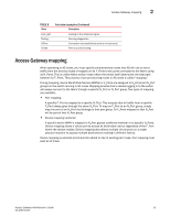
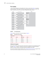
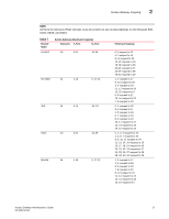
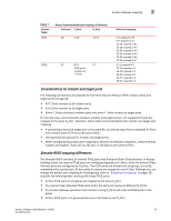
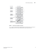
Access Gateway mapping 2 TABLE 7 Brocade Model 6510 Access Gateway default port mapping (Continued) Total ports F_Ports N_Ports 48 0-39 40-47 8000 32 8-31 0-7 FCoE ports mapped as F_Ports. Default port mapping 0-4 mapped to 40 5-9 mapped to 41 10-14 mapped to 42 15-19 mapped to 43 20-24 mapped to 44 25-29 mapped to 45 30-34 mapped to 46 35-39 mapped to 47 8-11 mapped to 0 12-15 mapped to 1 16-19 mapped to 2 20-23 mapped to 3 24-27 mapped to 4 28-31 mapped to 5 Considerations for initiator and target ports The following connections are possible for the Fibre Channel Protocol (FCP) initiator (host) and target ports through AG: • All F_Ports connect to all initiator ports. • All F_Ports connect to all target ports. • Some F_Ports connect to initiator ports and some F_Ports connect to target ports. For the last case, communication between initiator and target ports is not supported if both are mapped to the same N_Port. Therefore, follow these recommendations for initiator and target port mapping: • If connecting a host and target port to the same AG, you should map them to separate N_Ports and connect those N_Ports to the same fabric. • Use separate port groups for initiator and target ports. • When configuring secondary port mapping for failover and failback situations, make sure that initiator and target F_Ports will not fail over or fail back to the same N_Port. Brocade 8000 mapping differences The Brocade 8000 contains 24 internal FCoE ports and 8 external Fibre Channel ports. In Access Gateway mode, the internal FCoE ports are configured logically as F_Ports, while the external Fibre Channel ports are configured as N_Ports. The FCoE ports are divided into six groups, or trunks, consisting of four ports each. All four ports in a group are mapped to one N_Port. Although you can change the default port mapping for these groups (refer to "Default port mapping" on page 16), consider the following when working with these FCoE ports: • All four FCoE ports in the group are mapped to the same N_Port. • You cannot map individual FCoE ports within the same port group to different N_Ports. • Any Access Gateway operation that involves moving F_Ports will move all FCoE ports in the group. • All four FCoE ports in a group will fail over or fail back to one N_Port. Access Gateway Administrator's Guide 19 53-1002743-01
-
 1
1 -
2
-
3
-
4
-
5
-
6
-
7
-
8
-
9
-
10
-
11
-
12
-
13
-
14
-
15
-
16
-
17
-
18
-
19
-
20
-
21
-
22
-
23
-
24
-
25
-
26
-
27
-
28
-
29
-
30
-
31
-
32
-
33
-
 34
34 -
 35
35 -
 36
36 -
 37
37 -
 38
38 -
 39
39 -
 40
40 -
 41
41 -
 42
42 -
 43
43 -
 44
44 -
45
-
46
-
47
-
48
-
49
-
50
-
51
-
52
-
53
-
54
-
55
-
56
-
57
-
58
-
59
-
60
-
61
-
62
-
63
-
64
-
65
-
66
-
67
-
68
-
69
-
70
-
71
-
72
-
73
-
74
-
75
-
76
-
77
-
78
-
79
-
80
-
81
-
82
-
83
-
84
-
85
-
86
-
87
-
88
-
89
-
90
-
91
-
92
-
93
-
94
-
95
-
96
-
97
-
98
-
99
-
100
-
101
-
102
-
103
-
104
-
105
-
106
-
107
-
108
 |
 |