Dell PowerConnect FCS624S Web Management Interface User Guide - Page 115
Apply, Reset, to retain the previous version data.
 |
View all Dell PowerConnect FCS624S manuals
Add to My Manuals
Save this manual to your list of manuals |
Page 115 highlights
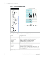
Configuring an Ethernet port 4 NOTE You may encounter connectivity errors if the stacking port configuration was not saved. Click Apply immediately after making stacking-related configuration changes, such as priority and stacking ports. Click Reset to undo the changes and then Click Apply to retain the previous version data. The configurable options shown in the Configure Ethernet Port display includes the following. Name Speed Duplex Status Flow Control Lock Address STP Fast Port STP Fast Uplink STP QOS DHCP Gateway ID Device Configuration Priority A port name can be assigned to help identify interfaces on the network. You can assign a port name to physical ports, virtual interfaces, and loopback interfaces. The parameter is an alphanumeric string. The name can be up to 64 characters long. The name can contain blanks. You do not need to use quotation marks around the string, even when it contains blanks. The 10/10/1000Base-T copper ports are designed to auto-sense and auto-negotiate the speed and mode of the connected device. If the attached device does not support this operation, you can manually enter the port speed to operate at either 10 Mbps or 100 Mbps. The default is auto. The port can be made inactive (disable) or active (enable) by selecting the appropriate status option. The default for a port is enabled. You can configure full-duplex ports on a system to operate with or without flow control. Flow control is enabled by default. Address-lock filters allow you to limit the number of devices that have access to a specific port. Access violations are reported as SNMP traps. By default this feature is disabled. A maximum of 2,048 entries can be specified for access. The default address count is eight. STP detects and eliminates logical loops in the network. STP also ensures that the least cost path is taken when multiple paths exist between ports or VLANs. If the selected path fails, STP searches for and then establishes an alternate path to prevent or limit retransmission of data. STP must be enabled at the system level to allow assignment of this capability on the VLAN level. You can determine if you want STP enabled or disabled at the port. You can determine if you want STP enabled or disabled at the uplink. You can select a port priority from 0 - 7. The router can assist DHCP or BootP Discovery packets from one subnet to reach DHCP or BootP servers on a different sub-net by placing the IP address of the router interface that receives the request in the request packet's Gateway field. Many power consuming devices advertise their power requirements to power sourcing devices. If you configure a port with a maximum power level or a power class for a power consuming device, the power level or power class takes precedence over the device's power requirement. You can configure an in-line power priority on ports, whereby ports with a higher in-line power priority will take precedence over ports with a low in-line power priority. The default is 3 (low priority). You can specify one of the following values: • 3 - low priority • 2 - high priority • 1 - critical priority PowerConnect B-Series FCX Web Management Interface User Guide 105 53-1002268-01
-
 1
1 -
2
-
3
-
4
-
5
-
6
-
7
-
8
-
9
-
10
-
11
-
12
-
13
-
14
-
15
-
16
-
17
-
18
-
19
-
20
-
21
-
22
-
23
-
24
-
25
-
26
-
27
-
28
-
29
-
30
-
31
-
32
-
33
-
34
-
35
-
36
-
37
-
38
-
39
-
40
-
41
-
42
-
43
-
44
-
45
-
46
-
47
-
48
-
49
-
50
-
51
-
52
-
53
-
54
-
55
-
56
-
57
-
58
-
59
-
60
-
61
-
62
-
63
-
64
-
65
-
66
-
67
-
68
-
69
-
70
-
71
-
72
-
73
-
74
-
75
-
76
-
77
-
78
-
79
-
80
-
81
-
82
-
83
-
84
-
85
-
86
-
87
-
88
-
89
-
90
-
91
-
92
-
93
-
94
-
95
-
96
-
97
-
98
-
99
-
100
-
101
-
102
-
103
-
104
-
105
-
106
-
107
-
108
-
109
-
 110
110 -
 111
111 -
 112
112 -
 113
113 -
 114
114 -
 115
115 -
 116
116 -
 117
117 -
 118
118 -
 119
119 -
 120
120 -
121
-
122
-
123
-
124
-
125
-
126
-
127
-
128
-
129
-
130
-
131
-
132
-
133
-
134
-
135
-
136
-
137
-
138
-
139
-
140
-
141
-
142
-
143
-
144
-
145
-
146
-
147
-
148
-
149
-
150
-
151
-
152
 |
 |
