Dell PowerEdge R910 Hardware Owner's Manual - Page 169
Grasp the system board using the handle and the card guides. Angle
 |
View all Dell PowerEdge R910 manuals
Add to My Manuals
Save this manual to your list of manuals |
Page 169 highlights
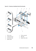
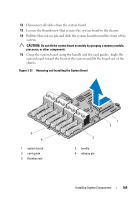
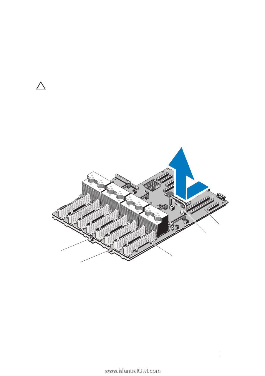
12 Disconnect all cables from the system board. 13 Loosen the thumbscrew that secures the system board to the chassis. 14 Pull the blue release pin and slide the system board toward the front of the system. CAUTION: Do not lift the system board assembly by grasping a memory module, processor, or other components. 15 Grasp the system board using the handle and the card guides. Angle the system board toward the front of the system and lift the board out of the chassis. Figure 3-37. Removing and Installing the System Board 5 4 1 system board 3 card guide 5 thumbscrew 3 2 handle 4 release pin 1 2 Installing System Components 169
-
 1
1 -
2
-
3
-
4
-
5
-
6
-
7
-
8
-
9
-
10
-
11
-
12
-
13
-
14
-
15
-
16
-
17
-
18
-
19
-
20
-
21
-
22
-
23
-
24
-
25
-
26
-
27
-
28
-
29
-
30
-
31
-
32
-
33
-
34
-
35
-
36
-
37
-
38
-
39
-
40
-
41
-
42
-
43
-
44
-
45
-
46
-
47
-
48
-
49
-
50
-
51
-
52
-
53
-
54
-
55
-
56
-
57
-
58
-
59
-
60
-
61
-
62
-
63
-
64
-
65
-
66
-
67
-
68
-
69
-
70
-
71
-
72
-
73
-
74
-
75
-
76
-
77
-
78
-
79
-
80
-
81
-
82
-
83
-
84
-
85
-
86
-
87
-
88
-
89
-
90
-
91
-
92
-
93
-
94
-
95
-
96
-
97
-
98
-
99
-
100
-
101
-
102
-
103
-
104
-
105
-
106
-
107
-
108
-
109
-
110
-
111
-
112
-
113
-
114
-
115
-
116
-
117
-
118
-
119
-
120
-
121
-
122
-
123
-
124
-
125
-
126
-
127
-
128
-
129
-
130
-
131
-
132
-
133
-
134
-
135
-
136
-
137
-
138
-
139
-
140
-
141
-
142
-
143
-
144
-
145
-
146
-
147
-
148
-
149
-
150
-
151
-
152
-
153
-
154
-
155
-
156
-
157
-
158
-
159
-
160
-
161
-
162
-
163
-
 164
164 -
 165
165 -
 166
166 -
 167
167 -
 168
168 -
 169
169 -
 170
170 -
 171
171 -
 172
172 -
 173
173 -
 174
174 -
175
-
176
-
177
-
178
-
179
-
180
-
181
-
182
-
183
-
184
-
185
-
186
-
187
-
188
-
189
-
190
-
191
-
192
-
193
-
194
-
195
-
196
-
197
-
198
-
199
-
200
-
201
-
202
-
203
-
204
-
205
-
206
-
207
-
208
-
209
-
210
 |
 |
Installing System Components
169
12
Disconnect all cables from the system board.
13
Loosen the thumbscrew that secures the system board to the chassis.
14
Pull the blue release pin and slide the system board toward the front of the
system.
CAUTION:
Do not lift the system board assembly by grasping a memory module,
processor, or other components.
15
Grasp the system board using the handle and the card guides. Angle the
system board toward the front of the system and lift the board out of the
chassis.
Figure 3-37.
Removing and Installing the System Board
1
system board
2
handle
3
card guide
4
release pin
5
thumbscrew
1
2
4
5
3