Dell PowerEdge R910 Hardware Owner's Manual - Page 20
PCI Express Generation 1 and, W or 750 W - usb
 |
View all Dell PowerEdge R910 manuals
Add to My Manuals
Save this manual to your list of manuals |
Page 20 highlights
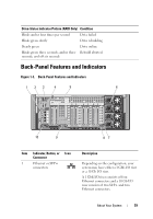
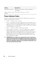
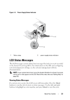
Item Indicator, Button, or Icon Connector 2 VFlash media slot (optional) 3 USB connectors (2) 4 iDRAC6 Enterprise port (optional) 5 PCIe expansion card slots (7) 6 Power supplies (4) 7 System identification connector 8 System identification button Description Connects an external SD memory card for the optional iDRAC6 Enterprise card. Connect USB devices to the system. The ports are USB 2.0-compliant. Dedicated management port for the optional iDRAC6 Enterprise card. PCI Express Generation 1 and Generation 2 Slot 1: PCIe x4 Gen2 half-length, full height Slot 2-4: PCIe x8 Gen2 half-length, full height Slot 5: PCIe x4 Gen1 half-length, full height Slot 6: PCIe x8 Gen2 half-length, full height Slot 7: PCIe x16 Gen2 half-length, half height NOTE: Slot 7 can be expanded to four additional PCIe x4 Gen2 low profile slots using an optional PCIe expansion riser. 1100 W or 750 W Connects the optional system status indicator assembly through the optional cable management arm. The identification buttons on the front and back panels can be used to locate a particular system within a rack. When one of these buttons is pushed, the LCD panel on the front and the blue system status indicator on the back blink until one of the buttons is pushed again. 20 About Your System
-
 1
1 -
2
-
3
-
4
-
5
-
6
-
7
-
8
-
9
-
10
-
11
-
12
-
13
-
14
-
 15
15 -
 16
16 -
 17
17 -
 18
18 -
 19
19 -
 20
20 -
 21
21 -
 22
22 -
 23
23 -
 24
24 -
 25
25 -
26
-
27
-
28
-
29
-
30
-
31
-
32
-
33
-
34
-
35
-
36
-
37
-
38
-
39
-
40
-
41
-
42
-
43
-
44
-
45
-
46
-
47
-
48
-
49
-
50
-
51
-
52
-
53
-
54
-
55
-
56
-
57
-
58
-
59
-
60
-
61
-
62
-
63
-
64
-
65
-
66
-
67
-
68
-
69
-
70
-
71
-
72
-
73
-
74
-
75
-
76
-
77
-
78
-
79
-
80
-
81
-
82
-
83
-
84
-
85
-
86
-
87
-
88
-
89
-
90
-
91
-
92
-
93
-
94
-
95
-
96
-
97
-
98
-
99
-
100
-
101
-
102
-
103
-
104
-
105
-
106
-
107
-
108
-
109
-
110
-
111
-
112
-
113
-
114
-
115
-
116
-
117
-
118
-
119
-
120
-
121
-
122
-
123
-
124
-
125
-
126
-
127
-
128
-
129
-
130
-
131
-
132
-
133
-
134
-
135
-
136
-
137
-
138
-
139
-
140
-
141
-
142
-
143
-
144
-
145
-
146
-
147
-
148
-
149
-
150
-
151
-
152
-
153
-
154
-
155
-
156
-
157
-
158
-
159
-
160
-
161
-
162
-
163
-
164
-
165
-
166
-
167
-
168
-
169
-
170
-
171
-
172
-
173
-
174
-
175
-
176
-
177
-
178
-
179
-
180
-
181
-
182
-
183
-
184
-
185
-
186
-
187
-
188
-
189
-
190
-
191
-
192
-
193
-
194
-
195
-
196
-
197
-
198
-
199
-
200
-
201
-
202
-
203
-
204
-
205
-
206
-
207
-
208
-
209
-
210
 |
 |