Dell Vostro 2510 Service Manual - Page 28
Processor Module: Dell Vostro 2510 <br>Service Manual, Removing the Processor Module
 |
View all Dell Vostro 2510 manuals
Add to My Manuals
Save this manual to your list of manuals |
Page 28 highlights
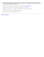
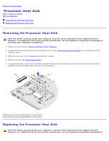
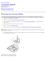
Back to Contents Page Processor Module Dell™ Vostro™ 2510 Service Manual Removing the Processor Module Replacing the Processor Module Removing the Processor Module CAUTION: Before working inside your computer, read the safety information that shipped with your computer. For additional safety best practices information, see the Regulatory Compliance Homepage at www.dell.com/regulatory_compliance. 1. Follow the instructions in Before Working on Your Computer. 2. Loosen the two screws that secure the memory cover. (See Removing a Memory Module for an illustration of the memory cover.) 3. Slide the cover out of the compartment and set it aside. 4. Remove the fan (see Removing the Fan). 5. Remove the processor thermal-cooling assembly (see Removing the Processor Thermal-Cooling Assembly). NOTICE: To avoid damage to the processor, hold the screwdriver so that it is perpendicular to the processor when turning the cam screw. 6. To loosen the ZIF socket, use a small, flat-blade screwdriver and rotate the ZIF-socket cam screw counterclockwise until it comes to the cam stop. 1 ZIF-socket cam screw 2 ZIF socket
-
 1
1 -
2
-
3
-
4
-
5
-
6
-
7
-
8
-
9
-
10
-
11
-
12
-
13
-
14
-
15
-
16
-
17
-
18
-
19
-
20
-
21
-
22
-
 23
23 -
 24
24 -
 25
25 -
 26
26 -
 27
27 -
 28
28 -
 29
29 -
 30
30 -
 31
31 -
 32
32 -
 33
33 -
34
-
35
-
36
-
37
-
38
-
39
-
40
-
41
-
42
-
43
-
44
-
45
-
46
-
47
-
48
-
49
-
50
-
51
-
52
-
53
-
54
-
55
-
56
-
57
-
58
-
59
-
60
-
61
-
62
-
63
-
64
-
65
-
66
-
67
-
68
-
69
-
70
-
71
-
72
 |
 |