Dell Vostro 2510 Service Manual - Page 45
Display Cable, Removing the Display Cable
 |
View all Dell Vostro 2510 manuals
Add to My Manuals
Save this manual to your list of manuals |
Page 45 highlights
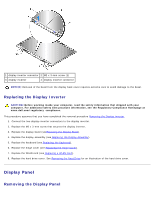
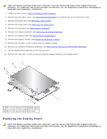
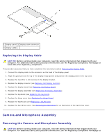
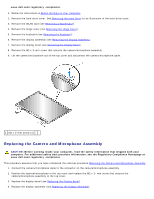
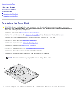
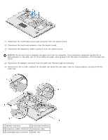
This procedure assumes that you have completed the removal procedure Removing the Display Panel. 1. Replace the eight M2 x 3-mm screws in the display panel. 2. Position the display panel assembly in the top cover. 3. Replace the camera/microphone assembly (see Replacing the Camera and Microphone Assembly). 4. Align the guide pins at the top of the display hinge panels and position the display panel in the top cover. 5. Replace the two M2 x 5-mm screws in the hinges. 6. Replace the display inverter (see Replacing the Display Inverter). 7. Replace the display bezel (see Replacing the Display Bezel). 8. Replace the display assembly (see Replacing the Display Assembly). 9. Replace the keyboard (see Replacing the Keyboard). 10. Replace the hinge cover (see Replacing the Hinge Cover). 11. Replace the WLAN card (see Replacing a WLAN Card). 12. Replace the hard drive cover. See Removing the Hard Drive for an illustration of the hard drive cover. Display Cable Removing the Display Cable CAUTION: Before working inside your computer, read the safety information that shipped with your computer. For additional safety best practices information, see the Regulatory Compliance Homepage at www.dell.com/regulatory_compliance. 1. Follow the instructions in Before Working on Your Computer. 2. Remove the hard drive cover. See Removing the Hard Drive for an illustration of the hard drive cover. 3. Remove the WLAN card (see Removing a WLAN Card). 4. Remove the hinge cover (see Removing the Hinge Cover). 5. Remove the keyboard (see Removing the Keyboard). 6. Remove the display assembly (see Removing the Display Assembly). 7. Remove the display bezel (see Removing the Display Bezel). 8. Remove the display inverter (see Removing the Display Inverter). 9. Remove the camera/microphone assembly (see Removing the Camera and Microphone Assembly). 10. Remove the two M2 x 5-mm screws from the display bracket. 11. Lift the display panel out of the top cover. 12. Disconnect the display cable from the connector on the back of the display panel.
-
 1
1 -
2
-
3
-
4
-
5
-
6
-
7
-
8
-
9
-
10
-
11
-
12
-
13
-
14
-
15
-
16
-
17
-
18
-
19
-
20
-
21
-
22
-
23
-
24
-
25
-
26
-
27
-
28
-
29
-
30
-
31
-
32
-
33
-
34
-
35
-
36
-
37
-
38
-
39
-
 40
40 -
 41
41 -
 42
42 -
 43
43 -
 44
44 -
 45
45 -
 46
46 -
 47
47 -
 48
48 -
 49
49 -
 50
50 -
51
-
52
-
53
-
54
-
55
-
56
-
57
-
58
-
59
-
60
-
61
-
62
-
63
-
64
-
65
-
66
-
67
-
68
-
69
-
70
-
71
-
72
 |
 |