Dell Vostro 2510 Service Manual - Page 59
Replacing the System Board Assembly
 |
View all Dell Vostro 2510 manuals
Add to My Manuals
Save this manual to your list of manuals |
Page 59 highlights
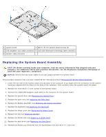
1 system board 2 M2.5 x 5-mm system board screws (3) 3 USB daughter-card cable connector 4 card with Bluetooth technology cable connector 5 speaker cable connector Replacing the System Board Assembly CAUTION: Before working inside your computer, read the safety information that shipped with your computer. For additional safety best practices information, see the Regulatory Compliance Homepage at www.dell.com/regulatory_compliance. NOTICE: Ensure that any loose cables do not get caught beneath the system board. This procedure assumes that you have completed the removal procedure Removing the System Board Assembly. 1. Insert the left side of the system board into the base of the computer at an angle until the connectors on the system board are aligned with the holes on the base of the computer, then carefully lower the system board into place. 2. Replace the three M2.5 x 5-mm screws on the system board. 3. Connect the 1394/USB daughter-card cable to the connector on the system board. 4. Replace the optical drive (see Replacing the Optical Drive). 5. Replace the palm rest (see Replacing the Palm Rest). 6. Replace the display assembly (see Replacing the Display Assembly). 7. Replace the keyboard (see Replacing the Keyboard). 8. Replace the hinge cover (see Replacing the Hinge Cover). 9. Replace the fan (see Replacing the Fan). 10. Replace the WLAN card (see Replacing a WLAN Card). 11. Replace the hard drive (see Replacing the Hard Drive). 12. Replace any blanks you removed from the ExpressCard slot and the 8-in-1 card slot.
-
 1
1 -
2
-
3
-
4
-
5
-
6
-
7
-
8
-
9
-
10
-
11
-
12
-
13
-
14
-
15
-
16
-
17
-
18
-
19
-
20
-
21
-
22
-
23
-
24
-
25
-
26
-
27
-
28
-
29
-
30
-
31
-
32
-
33
-
34
-
35
-
36
-
37
-
38
-
39
-
40
-
41
-
42
-
43
-
44
-
45
-
46
-
47
-
48
-
49
-
50
-
51
-
52
-
53
-
 54
54 -
 55
55 -
 56
56 -
 57
57 -
 58
58 -
 59
59 -
 60
60 -
 61
61 -
 62
62 -
 63
63 -
 64
64 -
65
-
66
-
67
-
68
-
69
-
70
-
71
-
72
 |
 |
