Dell XPS /Dimension Gen 5 Owner's Manual - Page 114
Set the processor lightly in the socket and ensure that the processor is level in the socket.
 |
View all Dell XPS /Dimension Gen 5 manuals
Add to My Manuals
Save this manual to your list of manuals |
Page 114 highlights
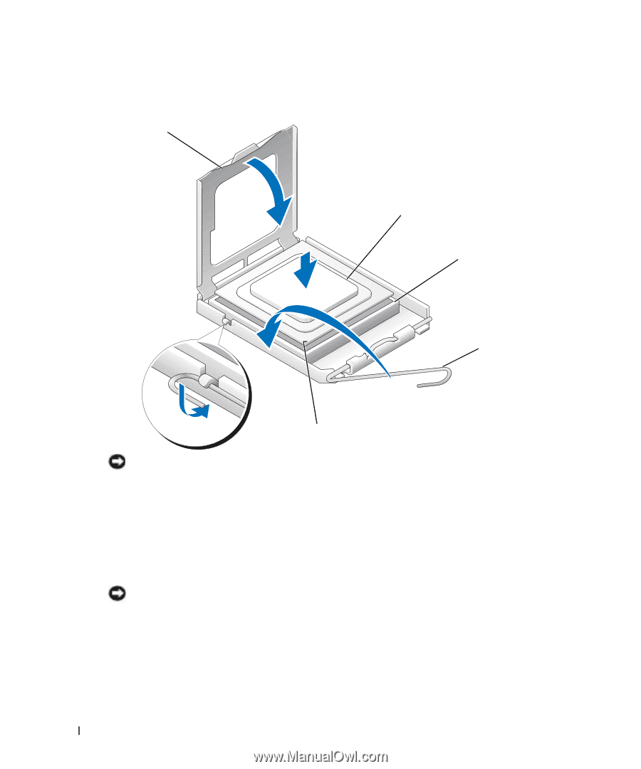
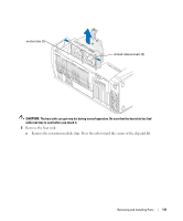
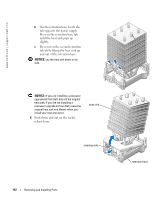
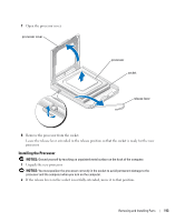
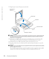
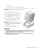
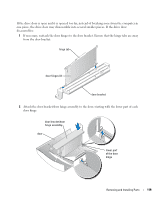
www.dell.com | support.dell.com 3 Align the pin-1 corner of the processor and socket. processor pin-1 indicator release lever processor processor socket socket pin-1 indicator NOTICE: Socket pins are delicate. To avoid damage, ensure that the processor is aligned properly with the socket, and do not use excessive force when you install the processor. Be careful not to touch or bend the pins on the system board. 4 Set the processor lightly in the socket and ensure that the processor is level in the socket. When the processor is positioned correctly, press it with minimal pressure to seat it. 5 When the processor is fully seated in the socket, close the processor cover. 6 Pivot the socket release lever back toward the socket and snap it into place to secure the processor. NOTICE: If you are not installing a processor upgrade kit from Dell, reuse the original heat sink assembly when you replace the processor. If you installed a processor replacement kit from Dell, return the original heat sink assembly and processor to Dell in the same package in which your replacement kit was sent. 114 Removing and Installing Parts
-
 1
1 -
2
-
3
-
4
-
5
-
6
-
7
-
8
-
9
-
10
-
11
-
12
-
13
-
14
-
15
-
16
-
17
-
18
-
19
-
20
-
21
-
22
-
23
-
24
-
25
-
26
-
27
-
28
-
29
-
30
-
31
-
32
-
33
-
34
-
35
-
36
-
37
-
38
-
39
-
40
-
41
-
42
-
43
-
44
-
45
-
46
-
47
-
48
-
49
-
50
-
51
-
52
-
53
-
54
-
55
-
56
-
57
-
58
-
59
-
60
-
61
-
62
-
63
-
64
-
65
-
66
-
67
-
68
-
69
-
70
-
71
-
72
-
73
-
74
-
75
-
76
-
77
-
78
-
79
-
80
-
81
-
82
-
83
-
84
-
85
-
86
-
87
-
88
-
89
-
90
-
91
-
92
-
93
-
94
-
95
-
96
-
97
-
98
-
99
-
100
-
101
-
102
-
103
-
104
-
105
-
106
-
107
-
108
-
 109
109 -
 110
110 -
 111
111 -
 112
112 -
 113
113 -
 114
114 -
 115
115 -
 116
116 -
 117
117 -
 118
118 -
 119
119 -
120
-
121
-
122
-
123
-
124
-
125
-
126
-
127
-
128
-
129
-
130
-
131
-
132
-
133
-
134
-
135
-
136
-
137
-
138
-
139
-
140
-
141
-
142
-
143
-
144
-
145
-
146
-
147
-
148
-
149
-
150
-
151
-
152
-
153
-
154
-
155
-
156
-
157
-
158
-
159
-
160
-
161
-
162
 |
 |