Dell XPS One 2720 XPS 27 2720 Owners Manual - Page 83
Replacing the Side-I/O Board, Procedure, Postrequisites
 |
View all Dell XPS One 2720 manuals
Add to My Manuals
Save this manual to your list of manuals |
Page 83 highlights
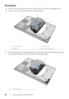
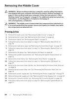
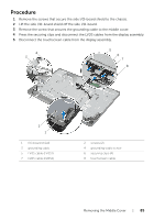
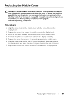
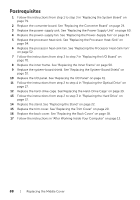
Replacing the Side-I/O Board WARNING: Before working inside your computer, read the safety information that shipped with your computer and follow the steps in "Before You Begin" on page 11. After working inside your computer, follow the instructions in "After Working Inside Your Computer" on page 13. For additional safety best practices information, see the Regulatory Compliance Homepage at dell.com/regulatory_compliance. Procedure 1 Slide the ports on the side I/O-board into the slots on the display bezel and align the screw holes on the side I/O-board with the screw holes on the display bezel. 2 Align the screw holes on the side I/O-board shield with the screw holes on the display bezel and place the side I/O-board shield on the side-I/O board. 3 Replace the screws that secure the side I/O-board shield to display bezel. NOTE: Ensure to secure the grounding cable with the same screw that secures the side I/O-shield to the display bezel. Postrequisites 1 Follow the instructions from step 1 to step 3 in "Replacing the System Board" on page 79. 2 Replace the processor heat-sink. See "Replacing the Processor Heat-Sink" on page 54. 3 Connect the antenna cables to the wireless mini-card. See "Replacing the Wireless Mini-Card" on page 46. 4 Follow the instructions from step 3 to step 7 in "Replacing the I/O Board" on page 70. 5 Replace the inner frame. See "Replacing the Inner Frame" on page 50. 6 Replace the system-board shield. See "Replacing the System-Board Shield" on page 32. 7 Replace the I/O panel. See "Replacing the I/O Panel" on page 41. 8 Replace the stand. See "Replacing the Stand" on page 22. 9 Replace the trim cover. See "Replacing the Trim Cover" on page 20. 10 Replace the back cover. See "Replacing the Back Cover" on page 18. 11 Follow the instructions in "After Working Inside Your Computer" on page 13. Replacing the Side-I/O Board | 83
-
 1
1 -
2
-
3
-
4
-
5
-
6
-
7
-
8
-
9
-
10
-
11
-
12
-
13
-
14
-
15
-
16
-
17
-
18
-
19
-
20
-
21
-
22
-
23
-
24
-
25
-
26
-
27
-
28
-
29
-
30
-
31
-
32
-
33
-
34
-
35
-
36
-
37
-
38
-
39
-
40
-
41
-
42
-
43
-
44
-
45
-
46
-
47
-
48
-
49
-
50
-
51
-
52
-
53
-
54
-
55
-
56
-
57
-
58
-
59
-
60
-
61
-
62
-
63
-
64
-
65
-
66
-
67
-
68
-
69
-
70
-
71
-
72
-
73
-
74
-
75
-
76
-
77
-
 78
78 -
 79
79 -
 80
80 -
 81
81 -
 82
82 -
 83
83 -
 84
84 -
 85
85 -
 86
86 -
 87
87 -
 88
88 -
89
-
90
-
91
-
92
-
93
-
94
-
95
-
96
-
97
-
98
-
99
-
100
-
101
-
102
-
103
-
104
-
105
-
106
-
107
-
108
-
109
-
110
-
111
-
112
-
113
-
114
-
115
-
116
-
117
 |
 |