Dell XPS One 2720 XPS 27 2720 Owners Manual - Page 97
Postrequisites, Replace the screw that secures the grounding cable from the right-speaker mesh
 |
View all Dell XPS One 2720 manuals
Add to My Manuals
Save this manual to your list of manuals |
Page 97 highlights
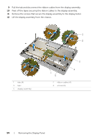
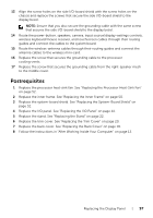
13 Align the screw holes on the side I/O-board shield with the screw holes on the chassis and replace the screws that secure the side I/O-board shield to the display bezel. NOTE: Ensure that you also secure the grounding cable with the same screw that secures the side I/O-board shield to the display bezel. 14 Route the power-button, speakers, camera, input source/display-settings controls, wireless keyboard/mouse receiver, and touchscreen cables through their routing guides and connect the cables to the system board. 15 Route the wireless-antenna cables through their routing guides and connect the antenna cables to the wireless mini-card. 16 Replace the screw that secures the grounding cable to the processor cooling-vents. 17 Replace the screw that secures the grounding cable from the right-speaker mesh to the middle cover. Postrequisites 1 Replace the processor heat-sink fan. See "Replacing the Processor Heat-Sink Fan" on page 52. 2 Replace the inner frame. See "Replacing the Inner Frame" on page 50. 3 Replace the system-board shield. See "Replacing the System-Board Shield" on page 32. 4 Replace the I/O panel. See "Replacing the I/O Panel" on page 41. 5 Replace the stand. See "Replacing the Stand" on page 22. 6 Replace the trim cover. See "Replacing the Trim Cover" on page 20. 7 Replace the back cover. See "Replacing the Back Cover" on page 18. 8 Follow the instructions in "After Working Inside Your Computer" on page 13. Replacing the Display Panel | 97
-
 1
1 -
2
-
3
-
4
-
5
-
6
-
7
-
8
-
9
-
10
-
11
-
12
-
13
-
14
-
15
-
16
-
17
-
18
-
19
-
20
-
21
-
22
-
23
-
24
-
25
-
26
-
27
-
28
-
29
-
30
-
31
-
32
-
33
-
34
-
35
-
36
-
37
-
38
-
39
-
40
-
41
-
42
-
43
-
44
-
45
-
46
-
47
-
48
-
49
-
50
-
51
-
52
-
53
-
54
-
55
-
56
-
57
-
58
-
59
-
60
-
61
-
62
-
63
-
64
-
65
-
66
-
67
-
68
-
69
-
70
-
71
-
72
-
73
-
74
-
75
-
76
-
77
-
78
-
79
-
80
-
81
-
82
-
83
-
84
-
85
-
86
-
87
-
88
-
89
-
90
-
91
-
 92
92 -
 93
93 -
 94
94 -
 95
95 -
 96
96 -
 97
97 -
 98
98 -
 99
99 -
 100
100 -
 101
101 -
 102
102 -
103
-
104
-
105
-
106
-
107
-
108
-
109
-
110
-
111
-
112
-
113
-
114
-
115
-
116
-
117
 |
 |