Dell XPS One 2720 XPS 27 2720 Owners Manual - Page 96
Replacing the Display Panel, Procedure
 |
View all Dell XPS One 2720 manuals
Add to My Manuals
Save this manual to your list of manuals |
Page 96 highlights
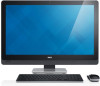
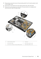
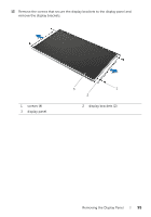
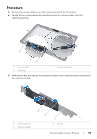
Replacing the Display Panel WARNING: Before working inside your computer, read the safety information that shipped with your computer and follow the steps in "Before You Begin" on page 11. After working inside your computer, follow the instructions in "After Working Inside Your Computer" on page 13. For additional safety best practices information, see the Regulatory Compliance Homepage at dell.com/regulatory_compliance. WARNING: The middle cover is heavy when the components are attached to it. It is recommended that two people remove and replace the middle cover while the components are attached to it. Procedure 1 Align the screw holes on the display brackets with the screw holes on the display panel. 2 Replace the screws that secure the display brackets to the display panel. 3 Align the screw holes on the display assembly with the screws holes on the display bezel and gently place the display assembly over the display bezel. NOTE: Ensure that no cables are placed under the display assembly. 4 Replace the screws that secure the display assembly to the display bezel. 5 Insert the ribbon cables into their connectors and press the tab to secure the cables. 6 Adhere the tapes that secure the ribbon cables to the display assembly. 7 Slide the ports on the side-I/O board into the slot on the display bezel and align the screw holes on the side-I/O board with the screw holes on the display bezel. WARNING: The middle cover is heavy when the components are attached to it. It is recommended that two people remove and replace the middle cover while the components are attached to it. 8 Using the hard-drive cage, align the bottom of the middle-cover assembly with the display bezel and lower the middle-cover assembly into the display bezel. 9 Route the LVDS and touchscreen cables through the slots in the middle cover. 10 Place the middle-cover assembly into the display bezel. NOTE: Ensure that all cables are routed through their routing guides and no cables are placed under the middle cover. 11 Align the screw holes on the middle cover with the screw holes on the display bezel. 12 Replace the screws that secure the middle-cover assembly to the display bezel. 96 | Replacing the Display Panel
-
 1
1 -
2
-
3
-
4
-
5
-
6
-
7
-
8
-
9
-
10
-
11
-
12
-
13
-
14
-
15
-
16
-
17
-
18
-
19
-
20
-
21
-
22
-
23
-
24
-
25
-
26
-
27
-
28
-
29
-
30
-
31
-
32
-
33
-
34
-
35
-
36
-
37
-
38
-
39
-
40
-
41
-
42
-
43
-
44
-
45
-
46
-
47
-
48
-
49
-
50
-
51
-
52
-
53
-
54
-
55
-
56
-
57
-
58
-
59
-
60
-
61
-
62
-
63
-
64
-
65
-
66
-
67
-
68
-
69
-
70
-
71
-
72
-
73
-
74
-
75
-
76
-
77
-
78
-
79
-
80
-
81
-
82
-
83
-
84
-
85
-
86
-
87
-
88
-
89
-
90
-
 91
91 -
 92
92 -
 93
93 -
 94
94 -
 95
95 -
 96
96 -
 97
97 -
 98
98 -
 99
99 -
 100
100 -
 101
101 -
102
-
103
-
104
-
105
-
106
-
107
-
108
-
109
-
110
-
111
-
112
-
113
-
114
-
115
-
116
-
117
 |
 |