Epson MX-80II User Manual - Page 18
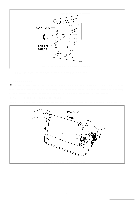
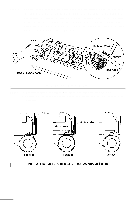
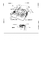
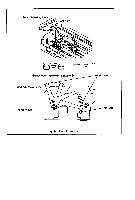
Fig. 13 Raising of Sprocket Lock Levers
 |
View all Epson MX-80II manuals
Add to My Manuals
Save this manual to your list of manuals |
Page 18 highlights
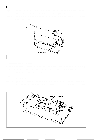
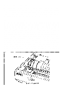
STEP 7. Raise the two sprocket lock levers to loosen, and adjust the sprocket pin position to the paper width. (See Fig. 13.) Fig. 13 Raising of Sprocket Lock Levers STEP 8. Engage the paper feed holes of the paper on the feeding pins, push the scale back into position, and adjust the tension of the paper. Then push the paper holding covers and the two sprocket lock levers down. (See Fig. 14.) NOTE: In this case, confirm that the feeding pins are centered in the respective paper feed holes of the paper. Fig. 14 Engagement of Paper Feed Holes on Feeding Pins -12-
-
 1
1 -
2
-
3
-
4
-
5
-
6
-
7
-
8
-
9
-
10
-
11
-
12
-
 13
13 -
 14
14 -
 15
15 -
 16
16 -
 17
17 -
 18
18 -
 19
19 -
 20
20 -
 21
21 -
 22
22 -
 23
23 -
24
-
25
-
26
-
27
-
28
-
29
-
30
-
31
-
32
-
33
-
34
-
35
-
36
-
37
-
38
-
39
-
40
-
41
-
42
-
43
-
44
-
45
-
46
-
47
-
48
-
49
-
50
-
51
-
52
-
53
-
54
-
55
-
56
-
57
-
58
-
59
-
60
-
61
-
62
-
63
-
64
-
65
-
66
-
67
-
68
-
69
-
70
-
71
-
72
-
73
-
74
-
75
-
76
-
77
-
78
-
79
-
80
-
81
-
82
-
83
-
84
-
85
-
86
-
87
-
88
-
89
-
90
-
91
-
92
-
93
-
94
-
95
-
96
-
97
-
98
-
99
-
100
-
101
-
102
-
103
 |
 |
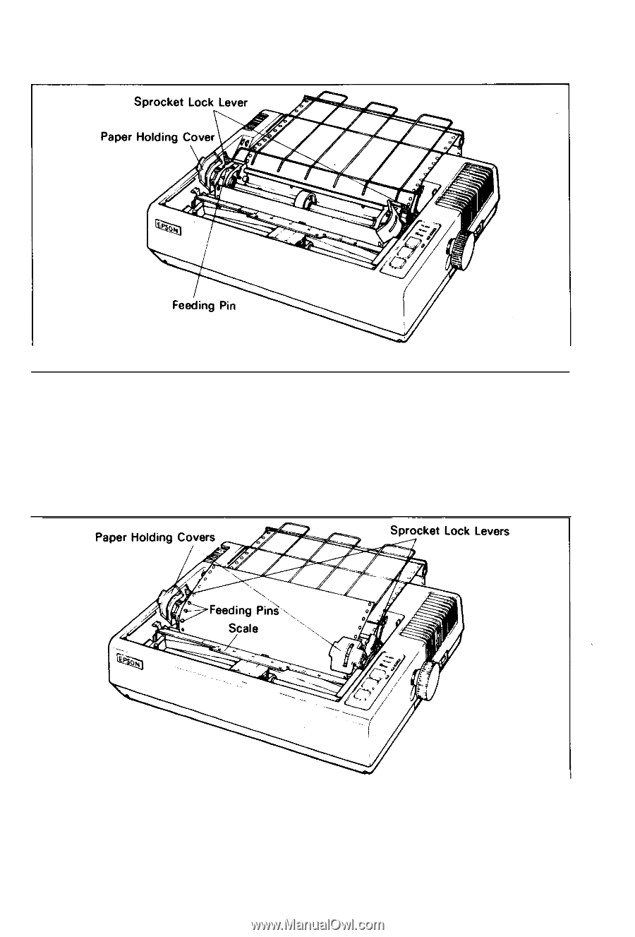
STEP 7.
Raise the two sprocket lock levers to loosen, and adjust the sprocket pin
position to the paper width. (See Fig. 13.)
Fig. 13 Raising of Sprocket Lock Levers
STEP 8.
Engage the paper feed holes of the paper on the feeding pins, push the
scale back into position, and adjust the tension of the paper. Then push
the paper holding covers and the two sprocket lock levers down. (See
Fig. 14.)
NOTE: In this case, confirm that the feeding pins are centered in the respective
paper feed holes of the paper.
Fig. 14 Engagement of Paper Feed Holes on Feeding Pins
-12-