Epson MX-80II User Manual - Page 94
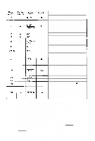
Table A2-2 Relations among ON-LINE, SLCT IN, DC 1/DC 3 and Interface Signal
 |
View all Epson MX-80II manuals
Add to My Manuals
Save this manual to your list of manuals |
Page 94 highlights
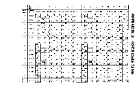
(4) Data transfer sequence Fig. A2-1 shows the sequence for data transmission. Relations among the ON LINE switch, SLCT IN signal, DC 1/DC 3 code and interface signals are shown in Table A2-2 below. Table A2-2 Relations among ON-LINE, SLCT IN, DC 1/DC 3 and Interface Signal -89-
-
 1
1 -
2
-
3
-
4
-
5
-
6
-
7
-
8
-
9
-
10
-
11
-
12
-
13
-
14
-
15
-
16
-
17
-
18
-
19
-
20
-
21
-
22
-
23
-
24
-
25
-
26
-
27
-
28
-
29
-
30
-
31
-
32
-
33
-
34
-
35
-
36
-
37
-
38
-
39
-
40
-
41
-
42
-
43
-
44
-
45
-
46
-
47
-
48
-
49
-
50
-
51
-
52
-
53
-
54
-
55
-
56
-
57
-
58
-
59
-
60
-
61
-
62
-
63
-
64
-
65
-
66
-
67
-
68
-
69
-
70
-
71
-
72
-
73
-
74
-
75
-
76
-
77
-
78
-
79
-
80
-
81
-
82
-
83
-
84
-
85
-
86
-
87
-
88
-
 89
89 -
 90
90 -
 91
91 -
 92
92 -
 93
93 -
 94
94 -
 95
95 -
 96
96 -
 97
97 -
 98
98 -
 99
99 -
100
-
101
-
102
-
103
 |
 |
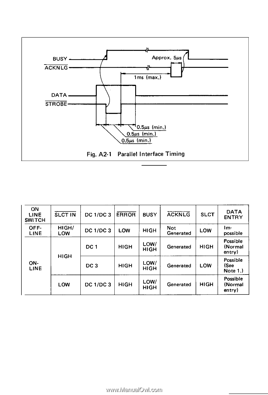
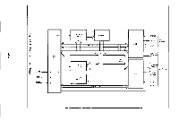
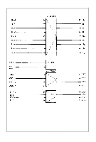
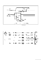
(4) Data transfer sequence
Fig. A2-1 shows the sequence for data transmission.
Relations among the ON LINE switch, SLCT IN signal, DC 1/DC 3 code and
interface signals are shown in Table A2-2 below.
Table A2-2 Relations among ON-LINE, SLCT IN, DC 1/DC 3 and Interface Signal
-89-