Epson MX-80II User Manual - Page 88
Appendix 1-construction Of Mx-80 Type Ii And Mx-80 F/t Type Ii, Appendix 1
 |
View all Epson MX-80II manuals
Add to My Manuals
Save this manual to your list of manuals |
Page 88 highlights
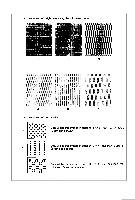
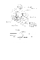
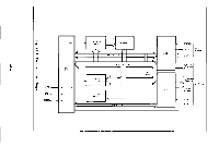
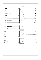
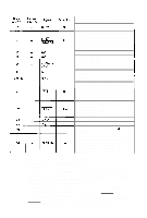
APPENDIX 1 Construction of MX-80 Type II and MX-80 F/T Type II The EPSON MX-80 Type I I and MX-80 F/T Type II dot matrix printers (hereinafter referred to as "Type II Printer") consist of the following three major functional blocks. (1) Printer Mechanism (2) Control Circuit Board (3) Power Circuit These three blocks are housed in a plastic case and are connected to one another. 1.1. Printer mechanism The printer mechanism has been developed by EPSON Shinshu Seiki CO ., Ltd., with the latest technology in the precision and electronic industry fields. The printer mechanism contains two stepper motors. One is to move the print head to the next print column position, and the other is to advance the paper. (1) Stepper motor for head carriage The stepper motor for head carriage is controlled under LSI "8041" called "slave CPU". The CPU knows the current printing position at any given time and the print head is stopped at the last printing position. Then, the CPU seeks the shortest travel way to the next print line. This feature and bidirectional printing enable the Printer to perform the logical seeking function which minimizes the head travel time to the next print line. (2) Stepper motor for paper feed Paper is fed by the stepper motor, like the head carriage. One complete rotation of the stepper motor corresponds to 1/3 inch paper advance, In the Type II Printer, the operator can select any paper feed length under software control. (3) Print head The print head has 9 dot wires to form 9 x 9 dot matrix characters. 9 wires form more legible characters than those formed by 7 wires. The print head for the printer mechanism is quite compact. 1.2. Control circuit board In this paragraph, the printer LSI circuitry is outlined. The control circuit diagram is shown in Fig. Al-l, and the driver circuit diagram in Fig. Al-2. -83-
-
 1
1 -
2
-
3
-
4
-
5
-
6
-
7
-
8
-
9
-
10
-
11
-
12
-
13
-
14
-
15
-
16
-
17
-
18
-
19
-
20
-
21
-
22
-
23
-
24
-
25
-
26
-
27
-
28
-
29
-
30
-
31
-
32
-
33
-
34
-
35
-
36
-
37
-
38
-
39
-
40
-
41
-
42
-
43
-
44
-
45
-
46
-
47
-
48
-
49
-
50
-
51
-
52
-
53
-
54
-
55
-
56
-
57
-
58
-
59
-
60
-
61
-
62
-
63
-
64
-
65
-
66
-
67
-
68
-
69
-
70
-
71
-
72
-
73
-
74
-
75
-
76
-
77
-
78
-
79
-
80
-
81
-
82
-
 83
83 -
 84
84 -
 85
85 -
 86
86 -
 87
87 -
 88
88 -
 89
89 -
 90
90 -
 91
91 -
 92
92 -
 93
93 -
94
-
95
-
96
-
97
-
98
-
99
-
100
-
101
-
102
-
103
 |
 |