Epson MX-80II User Manual - Page 66
LPRINT CHR$27; CHR$65; CHR$24, between any two dot wires of the print head is 1/72 inch
 |
View all Epson MX-80II manuals
Add to My Manuals
Save this manual to your list of manuals |
Page 66 highlights
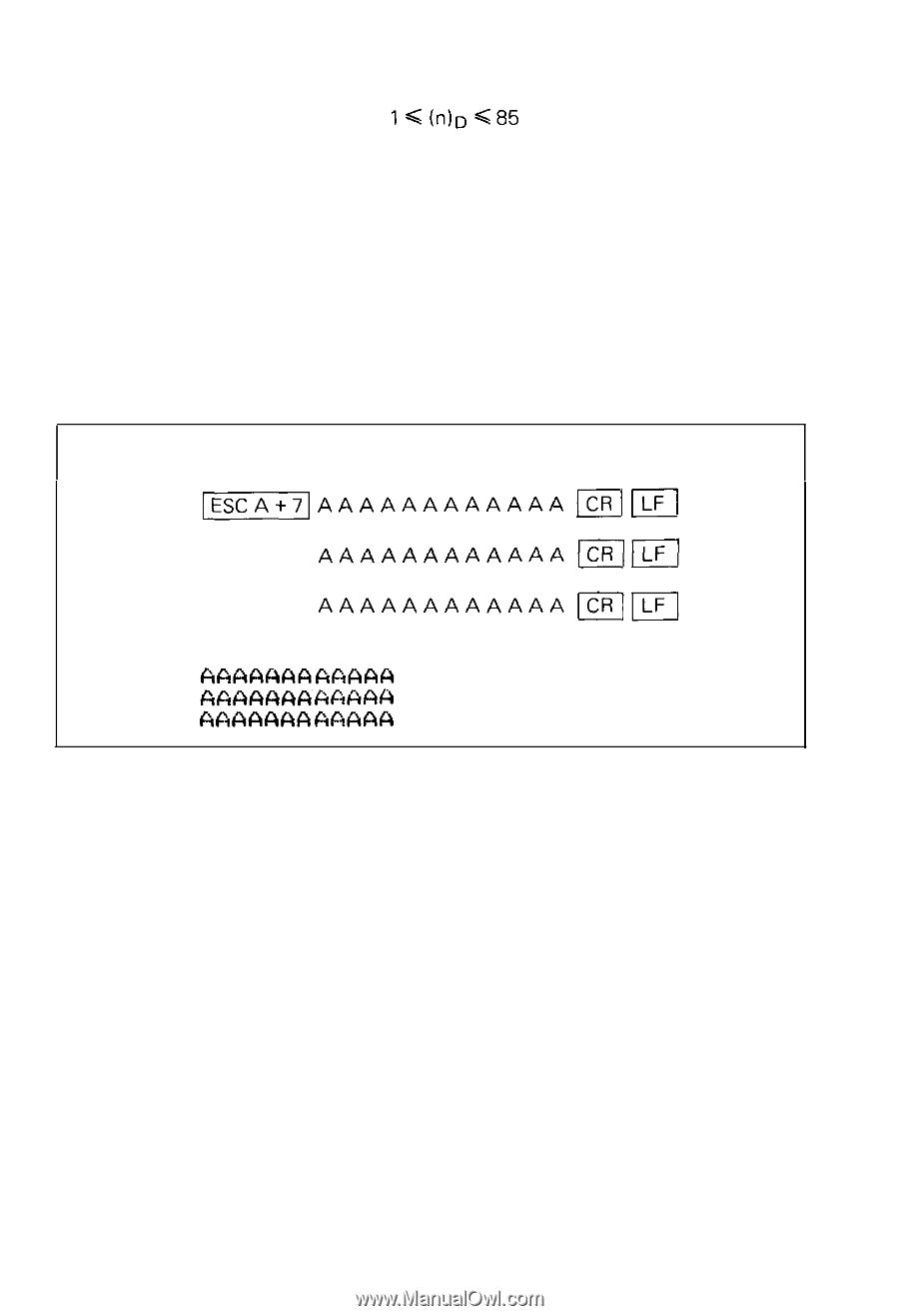
(4) ESC A + n (for setting amount of line spacing) This code specifies the amount of line spacing in the Line Feed, provided that ( n )D must satisfy the condition: (Decimal). " n " = 1 is equivalent to 1/72 inch paper advancement. Since the distance between any two dot wires of the print head is 1/72 inch, any line spacing in increments proportional to the distance between the dot wires can be established. NOTES: 1. When the POWER switch is turned on or INIT signal is applied to the pin No. 31 of the interface connector, the line spacing is set at either 1/8 inch or 1/6 inch according to the ON/OFF position of the DIP switch pin 1-1 on the control circuit board. 2. The ESC A + n code may be input at any position on a line. However, once the code is input, the specified amount of line spacing will remain un- changed until a code for new line spacing is set. (Example) To specify the amount of line spacing at 7/72 inches. [DATA] [PRINT) NOTE: When "n" is actually transferred to the Printer as data, it is transferred in the form of a 7-bit binary number. In case of "ESC A + 24" to specify the amount of line spacing at 24/72 = 1/3 inch (24 = (00011OOO)2), actual output to the Printer is performed as H H H in hexadecimal code. Keep in mind that the method of input from the keyboard of a host computer is different, for which refer to the specifications of your host computer. l Example: Input from the keyboard of the TRS-80 personal computer. [LPRINT CHR$(27); CHR$(65); CHR$(24)) -6O-
-
 1
1 -
2
-
3
-
4
-
5
-
6
-
7
-
8
-
9
-
10
-
11
-
12
-
13
-
14
-
15
-
16
-
17
-
18
-
19
-
20
-
21
-
22
-
23
-
24
-
25
-
26
-
27
-
28
-
29
-
30
-
31
-
32
-
33
-
34
-
35
-
36
-
37
-
38
-
39
-
40
-
41
-
42
-
43
-
44
-
45
-
46
-
47
-
48
-
49
-
50
-
51
-
52
-
53
-
54
-
55
-
56
-
57
-
58
-
59
-
60
-
 61
61 -
 62
62 -
 63
63 -
 64
64 -
 65
65 -
 66
66 -
 67
67 -
 68
68 -
 69
69 -
 70
70 -
 71
71 -
72
-
73
-
74
-
75
-
76
-
77
-
78
-
79
-
80
-
81
-
82
-
83
-
84
-
85
-
86
-
87
-
88
-
89
-
90
-
91
-
92
-
93
-
94
-
95
-
96
-
97
-
98
-
99
-
100
-
101
-
102
-
103
 |
 |