Epson MX-80II User Manual - Page 74
Normal-density bit image mode setting by ESC K + nl + n2
 |
View all Epson MX-80II manuals
Add to My Manuals
Save this manual to your list of manuals |
Page 74 highlights
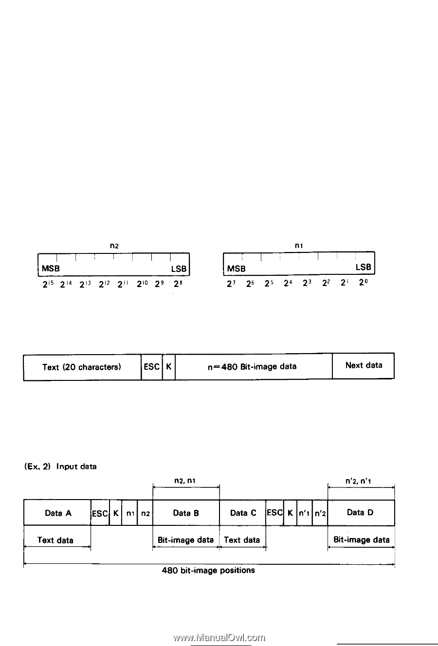
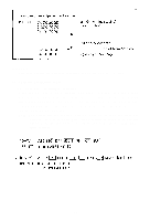
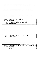
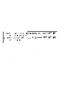
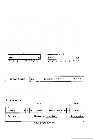
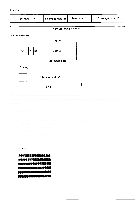
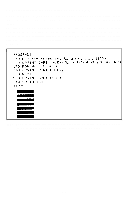
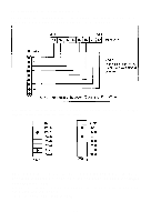
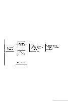
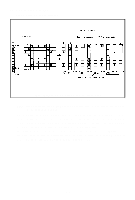
4.1. Normal-density bit image mode setting by ESC K + nl + n2 To convert the printer's operation mode from Text to Normal-density Bit Image, t h e " E S C K + nI + n2" code must be input. (Here, the sign "+" is inserted for the purpose of legibility only and should not be input in actual operation.) Namely, w h e n E S C ( < 1 B >H) a n d K ( < 4 B > H) c o d e s a n d d a t a n l a n d n2 a r e i n p u t , t h e Printer recognizes the data following the "ESC K" as the bit image data. nl and n2 are the hexadecimal numbers each consisting of 2 digits which define the amount of the bit image data to be transferred. n1 represents the low-order two digits while n2 represents the high-order two digits. In the normal-density bit image processing, the maximum number of dot positions printable per line is 480. Therefore, the values of nl and n2 specified in excess of 480 dot positions are ignored and printing of the bit image data after the 480th dot position is not guaranteed. Mixing of text data and bit image data is possible on the same line. NOTE: Assign values to n1 and n2, respectively as follows. As shown above, n1 is set hexadecimally as low-order bytes and n2 as high-order bytes. (Ex. 1) Input data 20 characters in text mode correspond to 120 bit-image positions (20 x 6 = 120). So the remaining printable positions in Bit-image mode are 360 (480 - 120 = 360). If 480 data are input as bit-image mode characters, the first 360 data can be printed but the remaining 120 data are ignored and thus not printed. -68-
-
 1
1 -
2
-
3
-
4
-
5
-
6
-
7
-
8
-
9
-
10
-
11
-
12
-
13
-
14
-
15
-
16
-
17
-
18
-
19
-
20
-
21
-
22
-
23
-
24
-
25
-
26
-
27
-
28
-
29
-
30
-
31
-
32
-
33
-
34
-
35
-
36
-
37
-
38
-
39
-
40
-
41
-
42
-
43
-
44
-
45
-
46
-
47
-
48
-
49
-
50
-
51
-
52
-
53
-
54
-
55
-
56
-
57
-
58
-
59
-
60
-
61
-
62
-
63
-
64
-
65
-
66
-
67
-
68
-
 69
69 -
 70
70 -
 71
71 -
 72
72 -
 73
73 -
 74
74 -
 75
75 -
 76
76 -
 77
77 -
 78
78 -
 79
79 -
80
-
81
-
82
-
83
-
84
-
85
-
86
-
87
-
88
-
89
-
90
-
91
-
92
-
93
-
94
-
95
-
96
-
97
-
98
-
99
-
100
-
101
-
102
-
103
 |
 |