Epson MX-80II User Manual - Page 92
Appendix 2-parallel Interface
 |
View all Epson MX-80II manuals
Add to My Manuals
Save this manual to your list of manuals |
Page 92 highlights
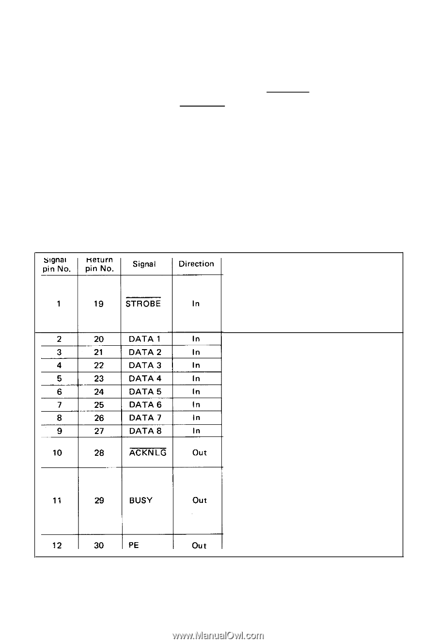
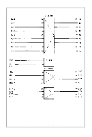
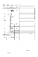
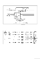
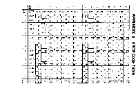
APPENDIX 2 Parallel Interface Both the MX-80 Type II and MX-80 F/T Type II include a parallel interface as the standard equipment, and this paragraph describes the parallel interface. (1) Specifications (a) Data transfer rate: 1000 CPS (min.) (b) Synchronization: By externally supplied STROBE pulses. (c) Handshaking: By ACKN LG or BUSY signals. (d) Logic level: Input data and all interface control signals are compatible with the TTL level. (2) Connector Plug: 57-30360 (AMPHENOL) It is recommended that interface cables be kept as short as possible. (3) Connector pin assignment and descriptions of signals. Connector pin assignment and descriptions of respective interface signals are provided in Table A2-1. Table A2-1 Connector Pin Assignment and Descriptions of Interface Signals Description STROBE pulse to read data in. Pulse width must be more than 0.5µs at receiving terminal. The signal level is normally "HIGH"; readin of data is performed at the "LOW" level of this signal. These signals represent information of the 1st to 8th bits of parallel data respectively. Each signal is at "HIGH" level when data is logical "I" and "LOW" when logical "0". Approx. 5µs pulse. "LOW" indicates that data has been received and that the printer is ready to accept other data. A "HIGH" signal indicates that the printer cannot receive data. The signal becomes "HIGH" in the following cases: 1. During data entry 2. During printing operation 3. In OFF-LINE state 4. During printer error status. A "HIGH" signal indicates that the printer is out of paper. -87-
-
 1
1 -
2
-
3
-
4
-
5
-
6
-
7
-
8
-
9
-
10
-
11
-
12
-
13
-
14
-
15
-
16
-
17
-
18
-
19
-
20
-
21
-
22
-
23
-
24
-
25
-
26
-
27
-
28
-
29
-
30
-
31
-
32
-
33
-
34
-
35
-
36
-
37
-
38
-
39
-
40
-
41
-
42
-
43
-
44
-
45
-
46
-
47
-
48
-
49
-
50
-
51
-
52
-
53
-
54
-
55
-
56
-
57
-
58
-
59
-
60
-
61
-
62
-
63
-
64
-
65
-
66
-
67
-
68
-
69
-
70
-
71
-
72
-
73
-
74
-
75
-
76
-
77
-
78
-
79
-
80
-
81
-
82
-
83
-
84
-
85
-
86
-
 87
87 -
 88
88 -
 89
89 -
 90
90 -
 91
91 -
 92
92 -
 93
93 -
 94
94 -
 95
95 -
 96
96 -
 97
97 -
98
-
99
-
100
-
101
-
102
-
103
 |
 |