Epson MX-80II User Manual - Page 73
Control Codes in the Bit Image Mode
 |
View all Epson MX-80II manuals
Add to My Manuals
Save this manual to your list of manuals |
Page 73 highlights
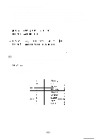
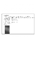
(7) NUL (Null) The NUL code is regarded as the termination for tabulation setting sequence. The lack of the NUL code would cause incorrect data printout. (8) ESC K Input of this code in the Text Mode causes the Printer's operation mode to be converted from Text to Normal-density Bit Image. Refer to paragraph 4.1, section 4, for details. (9) ESC L Input of this code in the Text Mode causes the Printer to perform dual-density bit image printing. Refer to paragraph 4.2, section 4, for details. 4. Control Codes in the Bit Image Mode Most of the abovementioned control codes are normally used in the text mode. Control codes associated with the Bit Image mode will be discussed next. Each computer has its unique way of handling graphics. For example, in the CBM computer there is a set of 64 special graphic characters that can be used to draw and plot with. On the other hand, the APPLE II computer has no graphic characters but a rich variety of graphic statements that allow you to control any dot in a 280-by-193 screen matrix. As well as the latter "APPLE II," the MX-80 Type II has no character generated graphics but allow you to control all the 8 needles freely and programmably by means of the so-called "Bit Image". To do that you have to switch the printer from the text mode to the bit image mode by inputting an escape code. This bit image mode expands the ability of the printer. The printer enters bit image mode when ESC K or ESC L code is input, and utilizes a raster scan technique that enables the printing of vertical columns of 8 dots across a page during each pass of the print head. To receive bit image data, RAM (128 bytes) of an IC on the control circuit board is used exclusively. When the bit image data received by the printer exceeds the RAM capacity, the printer will start printing bit image data from the first-in data, so that the RAM may always be filled up with data up to its capacity of 128 bytes. -67-
-
 1
1 -
2
-
3
-
4
-
5
-
6
-
7
-
8
-
9
-
10
-
11
-
12
-
13
-
14
-
15
-
16
-
17
-
18
-
19
-
20
-
21
-
22
-
23
-
24
-
25
-
26
-
27
-
28
-
29
-
30
-
31
-
32
-
33
-
34
-
35
-
36
-
37
-
38
-
39
-
40
-
41
-
42
-
43
-
44
-
45
-
46
-
47
-
48
-
49
-
50
-
51
-
52
-
53
-
54
-
55
-
56
-
57
-
58
-
59
-
60
-
61
-
62
-
63
-
64
-
65
-
66
-
67
-
 68
68 -
 69
69 -
 70
70 -
 71
71 -
 72
72 -
 73
73 -
 74
74 -
 75
75 -
 76
76 -
 77
77 -
 78
78 -
79
-
80
-
81
-
82
-
83
-
84
-
85
-
86
-
87
-
88
-
89
-
90
-
91
-
92
-
93
-
94
-
95
-
96
-
97
-
98
-
99
-
100
-
101
-
102
-
103
 |
 |