Fluke 1586A/2HC Product Manual - Page 12
Data Storage, Alarms, Digital I/O DIO, Totalizer, Remote Operation, Automated Sensor Test, DAQ-STAQ
 |
View all Fluke 1586A/2HC manuals
Add to My Manuals
Save this manual to your list of manuals |
Page 12 highlights
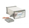
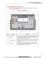
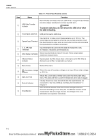
1586A Users Manual • Data Storage - Store up to 20 MB of data and channel setup files directly to the internal non-volatile memory or an external USB drive. Data can also be transferred to a PC with a USB drive or LAN TCP/IP interface at the rear of the unit with SCPI interface command sets. • Alarms - Each channel can be assigned two independent alarms to indicate when either an upper (HI) or lower (LO) range has been exceeded. The alarms can be configured to output a digital signal from the rear-panel alarm output for control of external devices. • Digital I/O (DIO) - The Product is equipped with a digital 8-bit transistor-transistor logic (TTL) port that can sense and output. When the DIO channel is included in the scan list, the value of this port is recorded in the scan data record on each scan with a value range of 0 to 255 based on the port state when it is read. • Totalizer - The Product is equipped with a unidirectional, resettable totalizer with an input count capability of 1,048,575 (20 bits). Counter increment is accomplished through a change to a digital signal or contact closure to the totalizer input terminals on the rear of the Instrument. • Remote Operation - Remotely operate the Product with remote SCPI commands from application software over a rear-panel USB or LAN TCP/IP connection. • Automated Sensor Test - Automatically sets the temperature of a Fluke Calibration dry-well calibrator or temperature bath connected to the rear-panel RS-232 port. Monitors temperature stability, and measures the readings of temperature sensors and a reference thermometer when the temperature is stable. • DAQ-STAQ Accessory - Multiplexer module provides quick and convenient connection of temperature sensors with Fluke's patented spring-loaded DWF terminals. 1-4 MyFlukeStore Shop for Fluke products online at: www. .com 1.888.610.7664
-
 1
1 -
2
-
3
-
4
-
5
-
6
-
 7
7 -
 8
8 -
 9
9 -
 10
10 -
 11
11 -
 12
12 -
 13
13 -
 14
14 -
 15
15 -
 16
16 -
 17
17 -
18
-
19
-
20
-
21
-
22
-
23
-
24
-
25
-
26
-
27
-
28
-
29
-
30
-
31
-
32
-
33
-
34
-
35
-
36
-
37
-
38
-
39
-
40
-
41
-
42
-
43
-
44
-
45
-
46
-
47
-
48
-
49
-
50
-
51
-
52
-
53
-
54
-
55
-
56
-
57
-
58
-
59
-
60
-
61
-
62
-
63
-
64
-
65
-
66
-
67
-
68
-
69
-
70
-
71
-
72
-
73
-
74
-
75
-
76
-
77
-
78
-
79
-
80
-
81
-
82
-
83
-
84
-
85
-
86
-
87
-
88
-
89
-
90
-
91
-
92
-
93
-
94
-
95
-
96
-
97
-
98
-
99
-
100
-
101
-
102
-
103
-
104
-
105
-
106
-
107
-
108
-
109
-
110
-
111
-
112
-
113
-
114
-
115
-
116
-
117
-
118
-
119
-
120
-
121
-
122
-
123
-
124
-
125
-
126
-
127
-
128
-
129
-
130
-
131
-
132
-
133
-
134
-
135
 |
 |