Fluke 1586A/2HC Product Manual - Page 15
Table 1-1. Front-Panel Features cont., Function, Table 1-2. Rear-Panel Features
 |
View all Fluke 1586A/2HC manuals
Add to My Manuals
Save this manual to your list of manuals |
Page 15 highlights
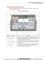
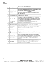
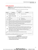
1 Product Overview and Specifications Front and Rear-Panel Overview Item Name Record Memory Measure/DMM Instrument Setup Channel Setup Numeric Keypad Table 1-1. Front-Panel Features (cont.) Function Starts and stops data recording. When recording, the key illuminates and "RECORDING" shows on the top of the display. Recording can be set to automatically start and stop with a scan. In addition to recording scan data, measurements made with the front-panel DMM can also be recorded. See Chapter 4 for more information and operation instructions. Manage setup files, scan data files, and DMM data files on either the internal memory or USB drive. Operate the single-channel measurement function or digital multimeter (DMM) function that lets the user quickly configure and make measurements with the front-panel inputs. See Chapter 5 for DMM operation instructions. Configure the Product. Menu contains many user-configurable settings to customize the Product. See "Configure the Product" in Chapter 2. Configure and verify channels. Channel Setup is the default menu that shows on the display when the Product is powered on. See Chapter 3 for instructions on how to wire and configure a channel. Use to input numerical values when prompted. Push and hold the PRINT or "0" key to take a screenshot of the display. Push and hold the LOCK key to lock the front panel to prevent changes and UNLOCK to unlock. Table 1-2. Rear-Panel Features 1 12 2 3 12345 67 8 12345 6 4 Item Name Line Voltage Selector and Fuse 5 6 7 8 9 10 11 Function hcn002.eps Regional voltage selector. See "Set the Regional Voltage" in Chapter 2. 1-7 MyFlukeStore Shop for Fluke products online at: www. .com 1.888.610.7664
-
 1
1 -
2
-
3
-
4
-
5
-
6
-
7
-
8
-
9
-
 10
10 -
 11
11 -
 12
12 -
 13
13 -
 14
14 -
 15
15 -
 16
16 -
 17
17 -
 18
18 -
 19
19 -
 20
20 -
21
-
22
-
23
-
24
-
25
-
26
-
27
-
28
-
29
-
30
-
31
-
32
-
33
-
34
-
35
-
36
-
37
-
38
-
39
-
40
-
41
-
42
-
43
-
44
-
45
-
46
-
47
-
48
-
49
-
50
-
51
-
52
-
53
-
54
-
55
-
56
-
57
-
58
-
59
-
60
-
61
-
62
-
63
-
64
-
65
-
66
-
67
-
68
-
69
-
70
-
71
-
72
-
73
-
74
-
75
-
76
-
77
-
78
-
79
-
80
-
81
-
82
-
83
-
84
-
85
-
86
-
87
-
88
-
89
-
90
-
91
-
92
-
93
-
94
-
95
-
96
-
97
-
98
-
99
-
100
-
101
-
102
-
103
-
104
-
105
-
106
-
107
-
108
-
109
-
110
-
111
-
112
-
113
-
114
-
115
-
116
-
117
-
118
-
119
-
120
-
121
-
122
-
123
-
124
-
125
-
126
-
127
-
128
-
129
-
130
-
131
-
132
-
133
-
134
-
135
 |
 |
