Fluke 1586A/2HC Product Manual - Page 37
Input Module and Relay Card Installation
 |
View all Fluke 1586A/2HC manuals
Add to My Manuals
Save this manual to your list of manuals |
Page 37 highlights
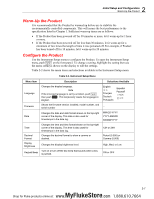
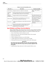
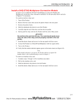
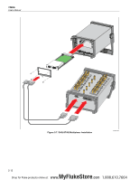
1586A Users Manual Menu Item Table 2-2. Instrument Setup Menu (cont.) Description Screen Saver Change the wait time or disable the screensaver. Calibration Date Password Management Shows the date that the Product was last calibrated. See the 1586A Calibration Manual for more information. Change the Admin and User profile passwords. Resume Scan Sets the Product to automatically turn on and resume scanning and recording after a power loss. Remote Port Configure the LAN Ethernet or serial USB communication settings. Shows how many times the channel relays have been Relay Counter scanned along with the name, serial number, and calibration date of the Input Module. Selections Available Never, 15 Min, 30 Min, or 60 Min -- See "Set Up Security" in this chapter for more information. See "Automatic Power Loss Scan Resume" in Chapter 4 for more information. See the 1586A Remote Programmers Guide for more information. -- Input Module and Relay Card Installation Before an Input Module can be inserted into the rear panel, a relay card must be installed. Standard product configurations include at least one slot preconfigured with a relay card. Use the procedure below and refer to Figure 2-6 as necessary to install the relay card: 1. Power off the Product with the main power switch. 2. Remove the four screws that secures the plastic frame to the rear panel. 3. Remove the plastic frame. 4. Slide the aluminum slot protector out of the Product. 5. Carefully align the rails of the relay card into the slot guides. 6. Slowly push the relay card into the Product until the card is fully seated. Caution Do not force the relay card into the slot. The card should easily move when the rails of the relay card are properly aligned in the slot guides. 7. Install the plastic frame and secure it to the rear panel with four screws. 2-8 MyFlukeStore Shop for Fluke products online at: www. .com 1.888.610.7664
-
 1
1 -
2
-
3
-
4
-
5
-
6
-
7
-
8
-
9
-
10
-
11
-
12
-
13
-
14
-
15
-
16
-
17
-
18
-
19
-
20
-
21
-
22
-
23
-
24
-
25
-
26
-
27
-
28
-
29
-
30
-
31
-
 32
32 -
 33
33 -
 34
34 -
 35
35 -
 36
36 -
 37
37 -
 38
38 -
 39
39 -
 40
40 -
 41
41 -
 42
42 -
43
-
44
-
45
-
46
-
47
-
48
-
49
-
50
-
51
-
52
-
53
-
54
-
55
-
56
-
57
-
58
-
59
-
60
-
61
-
62
-
63
-
64
-
65
-
66
-
67
-
68
-
69
-
70
-
71
-
72
-
73
-
74
-
75
-
76
-
77
-
78
-
79
-
80
-
81
-
82
-
83
-
84
-
85
-
86
-
87
-
88
-
89
-
90
-
91
-
92
-
93
-
94
-
95
-
96
-
97
-
98
-
99
-
100
-
101
-
102
-
103
-
104
-
105
-
106
-
107
-
108
-
109
-
110
-
111
-
112
-
113
-
114
-
115
-
116
-
117
-
118
-
119
-
120
-
121
-
122
-
123
-
124
-
125
-
126
-
127
-
128
-
129
-
130
-
131
-
132
-
133
-
134
-
135
 |
 |