Fluke 1586A/2HC Product Manual - Page 52
Caution, To prevent damage to the module, never turn the cover locks, more than quarter of a turn.
 |
View all Fluke 1586A/2HC manuals
Add to My Manuals
Save this manual to your list of manuals |
Page 52 highlights
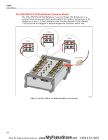
3 Input and Channel Configuration Input Wiring 2. Squeeze together the release tabs located on both sides of the Input Module then pull the module out of the Product. 3. Use a straight-head screw driver to rotate the cover locks to the unlock position then open the cover. Caution To prevent damage to the module, never turn the cover locks more than quarter of a turn. 4. Connect the positive source wire to the H terminal and the negative source wire to the L terminal. For 3-wire and 4-wire sense connections, connect the sense wires to the terminals directly across from the source wires. See "Sense Input Configuration" on page 3-6. 5. Route the wires through the strain-relief pins then out the back of the Input Module. If necessary, the rubber wire compressor used to secure the wires can be removed for more room. 6. Close the Input Module cover and rotate the cover locks to the locked position. 7. Align the Input Module on the guide rails and carefully slide the module into the connector at the rear of the Product until it latches in place. 8. Power on the Product with the main power switch. After powered on, the Product tests the connection to the Input Module. If the Input Module is recognized, the module indicator changes to green and shows all channels available on the left side of the Channel Setup menu as shown in Figure 3-4. If the module indicator does not turn green, refer to the troubleshooting information in Chapter 4. 9. Configure the channel. For instructions on how to configure the various input types, see "Channel Configuration" on page 3-10. Channel List Slot 1 Slot 2 Module Installed Empty Figure 3-4. Module Indicator (Input Module Installed Shown) hcn016.eps 3-9 MyFlukeStore Shop for Fluke products online at: www. .com 1.888.610.7664
-
 1
1 -
2
-
3
-
4
-
5
-
6
-
7
-
8
-
9
-
10
-
11
-
12
-
13
-
14
-
15
-
16
-
17
-
18
-
19
-
20
-
21
-
22
-
23
-
24
-
25
-
26
-
27
-
28
-
29
-
30
-
31
-
32
-
33
-
34
-
35
-
36
-
37
-
38
-
39
-
40
-
41
-
42
-
43
-
44
-
45
-
46
-
 47
47 -
 48
48 -
 49
49 -
 50
50 -
 51
51 -
 52
52 -
 53
53 -
 54
54 -
 55
55 -
 56
56 -
 57
57 -
58
-
59
-
60
-
61
-
62
-
63
-
64
-
65
-
66
-
67
-
68
-
69
-
70
-
71
-
72
-
73
-
74
-
75
-
76
-
77
-
78
-
79
-
80
-
81
-
82
-
83
-
84
-
85
-
86
-
87
-
88
-
89
-
90
-
91
-
92
-
93
-
94
-
95
-
96
-
97
-
98
-
99
-
100
-
101
-
102
-
103
-
104
-
105
-
106
-
107
-
108
-
109
-
110
-
111
-
112
-
113
-
114
-
115
-
116
-
117
-
118
-
119
-
120
-
121
-
122
-
123
-
124
-
125
-
126
-
127
-
128
-
129
-
130
-
131
-
132
-
133
-
134
-
135
 |
 |
