Fluke 1586A/2HC Product Manual - Page 75
Setpoint, Output
 |
View all Fluke 1586A/2HC manuals
Add to My Manuals
Save this manual to your list of manuals |
Page 75 highlights
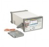
1586A Users Manual 5. Highlight High or Low then push . 6. Use the numeric keypad to input the limit (Setpoint). 7. To turn on an alarm output: a. Highlight Output the then push . b. Highlight an alarm output to assign to the channel then push . Terminal GND 1 2 3 4 5 6 TRIG Function Ground Terminal Alarm Output 1 Alarm Output 2 Alarm Output 3 Alarm Output 4 Alarm Output 5 Alarm Output 6 External Trigger Input Figure 3-10. Rear-Panel Alarm Outputs Alarm Setup hcn049.eps Alarm Indicator Monitor Screen Alarm output 3 low limit set to 2 V dc Rear View Lower-limit exceeded, alarm output 3 outputs
-
 1
1 -
2
-
3
-
4
-
5
-
6
-
7
-
8
-
9
-
10
-
11
-
12
-
13
-
14
-
15
-
16
-
17
-
18
-
19
-
20
-
21
-
22
-
23
-
24
-
25
-
26
-
27
-
28
-
29
-
30
-
31
-
32
-
33
-
34
-
35
-
36
-
37
-
38
-
39
-
40
-
41
-
42
-
43
-
44
-
45
-
46
-
47
-
48
-
49
-
50
-
51
-
52
-
53
-
54
-
55
-
56
-
57
-
58
-
59
-
60
-
61
-
62
-
63
-
64
-
65
-
66
-
67
-
68
-
69
-
 70
70 -
 71
71 -
 72
72 -
 73
73 -
 74
74 -
 75
75 -
 76
76 -
 77
77 -
 78
78 -
 79
79 -
 80
80 -
81
-
82
-
83
-
84
-
85
-
86
-
87
-
88
-
89
-
90
-
91
-
92
-
93
-
94
-
95
-
96
-
97
-
98
-
99
-
100
-
101
-
102
-
103
-
104
-
105
-
106
-
107
-
108
-
109
-
110
-
111
-
112
-
113
-
114
-
115
-
116
-
117
-
118
-
119
-
120
-
121
-
122
-
123
-
124
-
125
-
126
-
127
-
128
-
129
-
130
-
131
-
132
-
133
-
134
-
135
 |
 |

1586A
Users Manual
3-32
5.
Highlight
High
or
Low
then push
.
6.
Use the numeric keypad to input the limit (
Setpoint
).
7.
To turn on an alarm output:
a.
Highlight
Output
the then push
.
b.
Highlight an alarm output to assign to the channel then push
.
Terminal
G
N
D
1
2
3
4
5
6
TRIG
Function
Gro
u
nd Terminal
Alarm O
u
tp
u
t 1
Alarm O
u
tp
u
t 2
Alarm O
u
tp
u
t 3
Alarm O
u
tp
u
t 4
Alarm O
u
tp
u
t 5
Alarm O
u
tp
u
t 6
External Trigger Inp
u
t
hcn049.eps
Figure 3-10. Rear-Panel Alarm Outputs
0
1
2
3
4
5
6
7
1
2
3
4
5
6
1
2
3
4
5
6
7
8
1
2
3
4
5
6
Alarm Setup
Lower-limit exceeded, alarm
output 3 outputs <0.7 V dc
Monitor Screen
Rear View
Alarm output 3 low limit set to 2 V dc
Alarm Indicator
= Low Condition (<0.7 V dc)
hcn041.eps
Figure 3-11. Alarm Output Example
Shop for Fluke products online at:
1.888.610.7664
www.
MyFlukeStore
.com