Harman Kardon AVR 745 Owners Manual - Page 10
docked in The Bridge, selecting the DMP/The Bridge - firmware
 |
View all Harman Kardon AVR 745 manuals
Add to My Manuals
Save this manual to your list of manuals |
Page 10 highlights
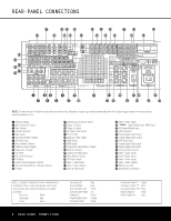
REAR-PANEL CONNECTIONS M HDMI Output: Connect this jack to the HDMI input on a compatible HDMI-equipped video display. N HDMI Inputs: Connect the HDMI output of video sources such as a DVD player, set-top box or HDTV tuner to either of these jacks. O Component Video Monitor Outputs: Connect these outputs to the component video inputs of a video display. P Multiroom IR Input: Connect the output of an IR sensor in a remote room to this jack to operate the AVR 745's multiroom control system. Q Component Video Inputs: These inputs may be used with any source device that is equipped with analog Y/Pr/Pb or RGB component video outputs, as assigned through the IN/OUT SETUP menu. See page 22 for more information on configuring the component video inputs. R Video Monitor Outputs: Connect these jacks to the composite or S-video input of a TV monitor or video projector to view the on-screen menus and the output of any standard video source selected by the receiver's video switcher. S DVD Video Inputs: Connect the composite or S-video outputs of a DVD player or other video source to these jacks. T Video 1 Video Inputs: Connect the composite or S-video PLAY/OUT jacks of a VCR or other video source to these jacks. U Video 1 Video Outputs: Connect the composite or S-video REC/IN jacks of a VCR or other video recording device such as a DVD recorder or PVR to these jacks. V Video 2 Video Inputs: Connect the composite or S-video PLAY/OUT jacks of a VCR or other video source to these jacks. W Video 3 Video Inputs: Connect the composite or S-video PLAY/OUT jacks of a VCR or other video source to these jacks. X TheBridgeTM Digital Media Player (DMP) Input: With the AVR 745 turned off, connect the optional Harman Kardon TheBridgeTM to this connector. Once this is done and with a compatible iPod® (optional) docked in The Bridge, selecting the DMP/The Bridge input allows you to play audio programming from the iPod and view navigation menus on the AVR's front panel and any video display connected to the AVR. You may control the iPod's functions and select tracks using the Set œ and Transport π buttons on the ZR 10 remote or with the "Listen to The Bridge" activity, which activates buttons on the TC 30 for direct control of your iPod through The Bridge. See page 45 for more information. Y XM-Ready Module Input: When an optional XM Connect & Play module is connected to this jack, and the XM service activated, you will be able to enjoy the XM Radio through your AVR 745. See page 46 for more information. Z USB Connector: Connect a cable with a USB "Mini B" connector to the AVR and the other end to a compatible computer running Windows® 2000, Windows® XP or higher with the latest service packs installed, to use this port to listen to audio from the computer through the AVR 745. This connection is also used to connect a compatible computer to the AVR for firmware upgrades, when available. See page 43 for more information on playback of computer audio with the AVR. Instructions for upgrades will accompany the upgrade file download package. a Optical Digital Audio Output: Connect this jack to the optical digital input connector on a CD-R/RW, MiniDisc or other compatible digital recorder. b Coaxial Digital Audio Output: Connect this jack to the coaxial digital input of a CD-R/RW, MiniDisc or other compatible digital recorder. c DVD Audio Inputs: Connect the left/right analog outputs of a DVD player or other audio source to these jacks. d Coaxial Digital Audio Inputs: Connect the coax digital output from a DVD player, HDTV receiver, LD player or CD player to these jacks. The signal may be a Dolby Digital signal, DTS signal or a standard PCM digital source. Do not connect the RF digital output of an LD player to these jacks. e Optical Digital Audio Inputs: Connect the optical digital output from a DVD player, HDTV receiver, LD player or CD player to these jacks. The signal may be a Dolby Digital signal, a DTS signal or a standard PCM digital source. f 8-Channel Direct Inputs: These jacks are used for connection to source devices such as high-resolution DVD players, DVD-Audio or SACD players with discrete analog audio outputs. Depending on the source device in use, all eight jacks may be used, though in many cases only connections to the front left/right, center, surround left/right and LFE (subwoofer input) jacks will be used for 5.1 audio signals. g Video 1 Audio Inputs: Connect the left/right PLAY/OUT audio output jacks on a VCR or other video source to these jacks. h Video 3 Audio Inputs: Connect the left/right PLAY/OUT audio output jacks on a VCR, PVR, cable set-top, satellite receiver, HDTV receiver or other video source to these jacks. i Video 2 Audio Inputs: Connect the left/right PLAY/OUT audio output jacks on a VCR or other video source to these jacks. j Video 1 Audio Outputs: Connect the left/right REC/IN audio input jacks on a VCR or other video source to these jacks. k FM Antenna Jack: Connect the supplied indoor or an optional external FM antenna to this terminal. l AM Antenna Connections: Connect the AM loop antenna supplied with the receiver to these terminals. If an external AM antenna is used, make connections to the AM and GND terminals in accordance with the instructions supplied with the antenna. 10 REAR-PANEL CONNECTIONS
-
 1
1 -
2
-
3
-
4
-
 5
5 -
 6
6 -
 7
7 -
 8
8 -
 9
9 -
 10
10 -
 11
11 -
 12
12 -
 13
13 -
 14
14 -
 15
15 -
16
-
17
-
18
-
19
-
20
-
21
-
22
-
23
-
24
-
25
-
26
-
27
-
28
-
29
-
30
-
31
-
32
-
33
-
34
-
35
-
36
-
37
-
38
-
39
-
40
-
41
-
42
-
43
-
44
-
45
-
46
-
47
-
48
-
49
-
50
-
51
-
52
-
53
-
54
-
55
-
56
-
57
-
58
-
59
-
60
 |
 |