Harman Kardon AVR 745 Owners Manual - Page 9
Surround Back/Multiroom Speaker Outputs - remote
 |
View all Harman Kardon AVR 745 manuals
Add to My Manuals
Save this manual to your list of manuals |
Page 9 highlights
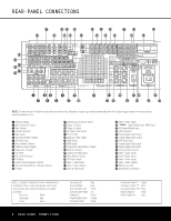
REAR-PANEL CONNECTIONS 0 Preamp Outputs: Connect these jacks to an optional, external power amplifier for applications where higher power is desired. 1 Main Subwoofer Output: Connect this jack to the line-level input of a powered subwoofer. If an external subwoofer amplifier is used, connect this jack to the subwoofer amplifier input. If only one subwoofer is used in your system, connect it here. 2 Tape Outputs: Connect these jacks to the Record/Input jacks of an audio recorder. 3 A-BUS Connector: Connect this jack to optional A-BUS®-certified products to extend the multiroom capabilities of your AVR 745. See page 17 for more information on A-BUS. 4 Tape Inputs: Connect these jacks to the Play/Out jacks of an audio recorder. 5 Surround Speaker Outputs: Connect these outputs to the matching + and - terminals on your surround channel speakers. In conformance with the CEA color-code specification, the blue terminal is the positive (+) terminal that should be connected to the red (+) terminal on the Surround Left speaker with older color-coding, while the gray terminal should be connected to the red (+) terminal on the Surround Right speaker with the older color-coding. Connect the black (-) terminal on the AVR to the matching black negative (-) terminals for each surround speaker. (See page 15 for more information on speaker polarity.) 6 CD Audio Inputs: Connect these jacks to the left/right analog audio output of a compact disc player or CD changer or other audio source. 7 Front Speaker Outputs: Connect these outputs to the matching + or - terminals on your left and right speakers. When making speaker connections, always make certain to maintain correct polarity by connecting the color-coded (white for front left and red for front right) (+) terminals on the AVR 745 to the red (+) terminals on the speakers and the black (-) terminals on the AVR 745 to the black (-) terminals on the speakers. See page 15 for more information on speaker polarity. 8 Multiroom Audio Outputs: Connect these jacks to the optional external audio power amplifier and video distribution system that delivers the source selected for multizone distribution. 9 Subwoofer 2 Output: If your system has two subwoofers, connect one to Main Subwoofer Output 1, and connect the line level input of a second subwoofer to this jack. A Fan Vents: These ventilation holes are the output of the AVR 745's airflow system. To ensure proper operation of the unit and to avoid possible damage to delicate surfaces, make certain that these holes are not blocked and that there is at least 3 inches of open space between the vent holes and any wooden or fabric surface. It is normal for the fan to remain off at most normal volume levels. An automatic temperature sensor turns the fan on only when it is needed. B Full Carrier IR Output: The output of this jack is the full signal received at the Remote Sensor Window ^ or input through the IR Input F including the carrier frequency that is removed from signals at the IR Output C. Use this output to extend IR remote signals to the input of compatible products by direct connection or through the use of optional, external IR "blasters". If you are in doubt as to which of the two IR Output jacks to use, we recommend that you consult with your dealer or installer, or check with the manufacturer of the external equipment you wish to control. C IR Output: This connection permits the IR sensor in the receiver to serve other remote controlled devices. Connect this jack to the "IR IN" jack on compatible Harman Kardon equipment. D Center Channel Speaker Outputs: Connect these outputs to the matching + and - terminals on your center channel speaker. In conformance with the CEA color-code specification, the green terminal is the positive (+) terminal that should be connected to the red (+) terminal on speakers with the older color-coding. Connect the black (-) terminal on the AVR to the black negative (-) terminal on your speaker. (See page 15 for more information on speaker polarity.) E Surround Back/Multiroom Speaker Outputs: These speaker terminals are normally used to power the surround back left/surround back right speakers in a 7.1-channel system. However, they may also be used to power the speakers in a second zone, which will receive the output selected for a multiroom system. To change the output fed to these terminals from the default of the Surround Back speakers to the Multiroom Output, you must change a setting in the Advanced Menu of the OSD system. See page 51 for more information on configuring this speaker output. In normal surround system use, the brown and black terminals are the surround back left channel positive (+) and negative (-) connections and the tan and black terminals are the surround back right positive (+) and negative (-) terminals. For multiroom use, connect the brown and black SBL terminals to the red and black connections on the left remote zone speaker and connect the tan and black SBR terminals to the red and black terminals on the right remote zone speaker. F IR Input: If the AVR 745's front-panel IR sensor is blocked due to cabinet doors or other obstructions, an external IR sensor may be used. Connect the output of the sensor to this jack. G Switched AC Accessory Outlet: This outlet may be used to power any device you wish to have turned on when the AVR 745 is turned on with the Standby/ On Switch 1. IMPORTANT NOTE: The power consumption of any device connected to the accessory outlet should not exceed 100 watts. Never connect high-power devices such as amplifiers or video displays to the accessory outlet. H Trigger 1 Output: Connect this jack to the "Trigger In" jack of an optional external component such as an audio power amplifier that you want to be controlled to mirror the power state of the AVR 745. When this connection is used, the AVR 745 will automatically send a low-voltage signal to the connected device that turns it on when the AVR 745 is on and off when the AVR 745 is placed in the Standby Mode. The connected component must respond to 6-volt presence as the control signal. I Trigger 2 Output: Connect this jack to the "Trigger In" jack of an optional, external component such as a projection screen or motorized blinds that you want to turn on or off in response to the power state of the AVR 745, but only when certain inputs are selected. (For example, lower a screen when a Video related mode is selected, but not for the tuner or a CD player.) For the 5-volt control signal to be sent to the jack for device control, you must activate the appropriate setting in PAGE 2 of the IN/OUT SETUP menu. See page 23 for more information. J AC Power Cord Socket: Connect the AC power cord here when the installation is complete. To ensure safe operation, use only the power cord supplied with the unit. If a replacement is required, it must be of the same type and capacity. K RS-232 Port: This jack may be used to control the AVR 745 over a bi-directional RS-232 serial control link to a compatible computer or programmable remote control system. Due to the complexity of programming RS-232 commands, we strongly recommend that connections to this port for control purposes be made by a trained and qualified technician or installer. L Multiroom Video Output: Connect this jack to the cable and/or optional, external video distribution system that delivers the video source selected for multizone distribution to remote rooms. Only composite video is available. REAR-PANEL CONNECTIONS 9
-
 1
1 -
2
-
3
-
 4
4 -
 5
5 -
 6
6 -
 7
7 -
 8
8 -
 9
9 -
 10
10 -
 11
11 -
 12
12 -
 13
13 -
 14
14 -
15
-
16
-
17
-
18
-
19
-
20
-
21
-
22
-
23
-
24
-
25
-
26
-
27
-
28
-
29
-
30
-
31
-
32
-
33
-
34
-
35
-
36
-
37
-
38
-
39
-
40
-
41
-
42
-
43
-
44
-
45
-
46
-
47
-
48
-
49
-
50
-
51
-
52
-
53
-
54
-
55
-
56
-
57
-
58
-
59
-
60
 |
 |
