Harman Kardon AVR 745 Owners Manual - Page 26
Original, Adjust1, Adjust2, Adjust3, Adjust4, Adjust5, Adjust6, Videomain, Mastermenu, Advanced,
 |
View all Harman Kardon AVR 745 manuals
Add to My Manuals
Save this manual to your list of manuals |
Page 26 highlights
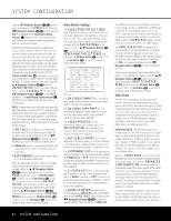
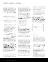
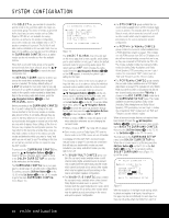
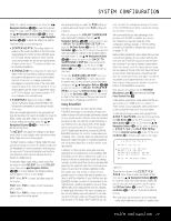
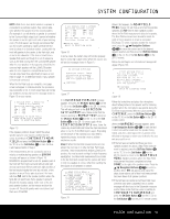
SYSTEM CONFIGURATION line, you are able to change the setting for the output aspect ratio. In most cases, the default setting of ORIGINAL provides the best result, but if the combination of program material, input source device capabilities and the adjustments available on your video display do not provide the desired picture format, press the ⁄/¤ Navigation Buttons D© to experiment with the six available options. • ADJUST 1 will stretch a 4:3 letterbox input vertically so that it fills a 16:9 screen. • ADJUST 2 will apply a nonlinear horizontal stretch of a full-screen 4:3 input to a 16:9 screen. When this option is chosen, objects will appear to be a bit "fatter," due to the stretch. • ADJUST 3 will process a 2.35:1 image that is formatted with a 4:3 letterbox and vertically stretch it to fill a 16:9 screen, but it will also crop the left and right sides of the image. • ADJUST 4 will process a 2.35:1 image that is formatted with a 4:3 letterbox and vertically stretch it to fill a 16:9 screen, with nonlinear horizontal processing so that the full image appears on the screen. To accomplish this, you will find that objects on the far left and right sides of the screen may appear to be "skinnier" than normal. • ADJUST 5 will apply a stretch to fit 4:3 fullscreen images to fill a 16:9 screen. • ADJUST 6 is an automatic mode that will apply the processing from ADJUST 3 to a letterbox input or ADJUST 2 to a full-screen 4:3 input. Once settings are made on the VIDEO MAIN menu, you may either return to the MASTER MENU or proceed to either of the two ADVANCED CONFIGURATION setting menus. The options on those pages are set by your choice on the SOURCE TYPE line, but you may change one or more of the settings to customize your video presentation. To return to the MAIN MENU, press the ⁄/¤ Navigation Buttons D© so that the onscreen cursor is pointing to BACK TO MASTER MENU and press the OK/Enter Button E or the Set Button œ. To change the settings on the ADVANCED CONFIGURATION menus, press the ⁄/¤ Navigation Button D © so that the on-screen cursor is pointing to ADVANCED CONFIG SET and press the OK/Enter Button E or the Set Button q. The first page of the ADVANCED CONFIGURATION menus (Figure 6) will appear on screen. Advanced Configuration Settings The Advanced Configuration Settings may be used to change the individual items that make up the default profile for each video input. You may change none, one or as many of the settings as you wish, to create the on-screen image that you prefer. As with all of the video settings, you can't "hurt" anything by experimenting with the settings, and while the defaults represent the result of extensive lab testing with a variety of display types, input sources and test signals, there is no "right" or "wrong" setting other than the ones that look best to you. The settings that are available on PAGE 1 of the ADVANCED CONFIGURATION menus (Figure 6) are all On/Off settings. On that page, use the ⁄/¤ Navigation Buttons D© to move the on-screen cursor next to the line for the setting you wish to change. Then, press the ‹/› Navigation Buttons D© to turn the setting on or off. *ADVANCED CONFIG PAGE1* → NOISE REDUCTION :ON X-COLOR SUPPRESSOR :ON DCDi INTERPOLATION :ON FILM MODE DETECT :ON FILM MODE EDIT DET :ON FLESHTONE NOIS RED :ON COMPNT VIDEO ENHANCE:ON TO VIDEO MAIN PAGE2 Figure 6 These settings are available on PAGE 1 of the ADVANCED CONFIGURATION menu: NOISE REDUCTION: When this setting is turned on, there is a reduction in the video noise that is often present in analog input sources. X-COLOR SUPPRESSOR: When this setting is on, there is a reduction in the cross-color interference that typically appears in composite video sources as moiré in finely detailed objects. DCDi INTERPOLATION: DCDi stands for Directional Correlation De-interlacing, and it is a Faroudja technology that examines each pixel for the optimal direction from which to interpolate the video information, with regard to local edges. This adaptive process prevents the appearance of staircasing and the jagged edges that are often visible with other means of de-interlacing. FILM MODE DETECT: When this setting is on, special circuits are used to detect the presence of film-originated material so that the original film-frame sequence may be recovered by weaving together the appropriate video fields. FILM MODE EDIT DETECT: When this setting is on, additional processing is applied when film-based material is detected so that any disruption in the frame sequence of film-based material due to video edits or the overlay of video text over film is compensated for by processing, before artifacts such as feathering may appear. FLESHTONE NOISE REDUCTION: When this setting is on, the processing is adapted to preserve the detail in faces and flesh tones while reducing noise in the total picture. COMPONENT VIDEO ENHANCE: When this setting is on, component video signals are processed to adjust the high-frequency content of the signal to offer enhanced depth in the picture, as well as greater small object detail. When all settings on this submenu page that require adjustment have been made, use the ⁄/¤ Navigation Buttons D© to move the onscreen cursor next to PAGE 2 and then press the OK/Enter Button E or the Set Button œ to move to the next page of the ADVANCED CONFIGURATION settings, or move the onscreen cursor next to the TO VIDEO MAIN line to return to the VIDEO MAIN menu. *ADVANCED CONFIG PAGE2* → TEST VIDEO OUT ASPECT BRIGHTNESS CONTRAST SATURATION RATIO :OFF :4:3 :100 :100 :100 TO VIDEO MAIN PAGE1 Figure 7 These settings are available on PAGE 2 of the ADVANCED CONFIGURATION menu (Figure 7): TEST VIDEO: The test signals that are called up on this line are designed for use in factory setup of the AVR 745's video processing circuit and they are not designed for user adjustment of any controls on your video sources, on your video display or on the AVR 745 itself. You may bypass this setting line unless you wish to view the signals, but remember that they are not designed for any consumer use. To view the test signals, with the on-screen cursor next to the TEST VIDEO line, press the ‹/› Navigation Buttons D© to select one of the test signals described below, and then press the OK/Enter Button E or the Set Button œ to activate the test signal. The test signal will remain on the screen for the length of time selected in the ADVANCED SETTINGS menu for the on-screen menus, as explained on page 50. The four test signals are: Color Bars: These are a variation of traditional split-field color bars used to check the internal settings for luminance/chrominance voltage levels with respect to the eight basic colors. 26 SYSTEM CONFIGURATION
-
 1
1 -
2
-
3
-
4
-
5
-
6
-
7
-
8
-
9
-
10
-
11
-
12
-
13
-
14
-
15
-
16
-
17
-
18
-
19
-
20
-
 21
21 -
 22
22 -
 23
23 -
 24
24 -
 25
25 -
 26
26 -
 27
27 -
 28
28 -
 29
29 -
 30
30 -
 31
31 -
32
-
33
-
34
-
35
-
36
-
37
-
38
-
39
-
40
-
41
-
42
-
43
-
44
-
45
-
46
-
47
-
48
-
49
-
50
-
51
-
52
-
53
-
54
-
55
-
56
-
57
-
58
-
59
-
60
 |
 |
