Harman Kardon AVR 745 Owners Manual - Page 8
Rear-panel Connections - usb
 |
View all Harman Kardon AVR 745 manuals
Add to My Manuals
Save this manual to your list of manuals |
Page 8 highlights
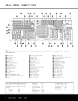
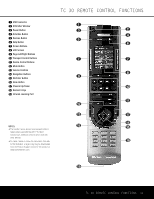
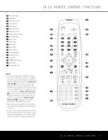
REAR-PANEL CONNECTIONS SUB 2 MODEL NO. AVR 745 NOTE: To make it easier to follow the instructions that refer to this illustration, a larger copy may be downloaded from the Product Support section for this product at www.harmankardon.com. 0 Preamp Outputs 1 Main Subwoofer Output 2 Tape Outputs 3 A-BUS Connector 4 Tape Inputs 5 Surround Speaker Outputs 6 CD Audio Input 7 Front Speaker Outputs 8 Multiroom Audio Outputs 9 Subwoofer 2 Output A Fan Vents B Full Carrier IR Output C IR Output D Center Channel Speaker Outputs E Surround Back/Multiroom Speaker Outputs F IR Input G Switched AC Accessory Outlet H Trigger 1 Output I Trigger 2 Output J AC Power Cord Socket K RS-232 Port L Multiroom Video Output M HDMI Output N HDMI Inputs O Component Video Monitor Outputs P Multiroom IR Input Q Component Video Inputs R Video Monitor Outputs S DVD Video Inputs T Video 1 Video Inputs U Video 1 Video Outputs V Video 2 Video Inputs W Video 3 Video Inputs X TheBridgeTM Digital Media Player (DMP) Input Y XM-Ready Module Input Z USB Connector a Optical Digital Audio Output b Coaxial Digital Audio Output c DVD Audio Inputs d Coaxial Digital Audio Inputs e Optical Digital Audio Inputs f 8-Channel Direct Inputs g Video 1 Audio Inputs h Video 3 Audio Inputs i Video 2 Audio Inputs j Video 1 Audio Outputs k FM Antenna Jack l AM Antenna Connections NOTE: To assist in making the correct connections for multichannel input, output and speaker connections, all connection jacks and terminals are color-coded as follows: Front Left: White Front Right: Red Center: Green Surround Left: Surround Right: Surround Back Left: Surround Back Right: Subwoofer: Coaxial Digital Audio: Composite Video: Blue Gray Brown Tan Purple Orange Yellow 8 REAR-PANEL CONNECTIONS Component Video "Y": Green Component Video "Pr": Red Component Video "Pb": Blue Optical Digital In: Black Optical Digital Out: Gray
-
 1
1 -
2
-
 3
3 -
 4
4 -
 5
5 -
 6
6 -
 7
7 -
 8
8 -
 9
9 -
 10
10 -
 11
11 -
 12
12 -
 13
13 -
14
-
15
-
16
-
17
-
18
-
19
-
20
-
21
-
22
-
23
-
24
-
25
-
26
-
27
-
28
-
29
-
30
-
31
-
32
-
33
-
34
-
35
-
36
-
37
-
38
-
39
-
40
-
41
-
42
-
43
-
44
-
45
-
46
-
47
-
48
-
49
-
50
-
51
-
52
-
53
-
54
-
55
-
56
-
57
-
58
-
59
-
60
 |
 |
