HP 6120XG HP ProCurve Series 6120 Blade Switches Installation and Getting Star - Page 24
Example high availability topology, Management and Configuration Guide
 |
View all HP 6120XG manuals
Add to My Manuals
Save this manual to your list of manuals |
Page 24 highlights
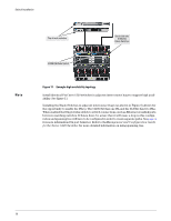
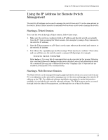
Switch Installation Top of rack switches 6120G/XG Blade Switch Server with two 6120G/XG Blade Switches Note Figure 11. Example high availability topology Install identical ProCurve 6120 switches in adjacent interconnect bays to support high availability. See figure 11. Installing the Blade Switches in adjacent interconnect bays (as shown in Figure 8) allows for the opportunity to enable the ISL(s). The 6120G/XG has one ISL and the 6120XG has two ISLs. When enabled the ISL provides switch to switch connections, such as Ethernet crosslink ports between matching switches. If this is done, be aware that it will cause a loop in this configuration and spanning tree will have to be configured in order to create separate paths. See page 4 for more information ISL port behavior. Refer to theManagement and Configuration Guide for the Series 6120 Switches for more detailed information on using spanning tree. 16
-
 1
1 -
2
-
3
-
4
-
5
-
6
-
7
-
8
-
9
-
10
-
11
-
12
-
13
-
14
-
15
-
16
-
17
-
18
-
 19
19 -
 20
20 -
 21
21 -
 22
22 -
 23
23 -
 24
24 -
 25
25 -
 26
26 -
 27
27 -
 28
28 -
 29
29 -
30
-
31
-
32
-
33
-
34
-
35
-
36
-
37
-
38
-
39
-
40
-
41
-
42
-
43
-
44
-
45
-
46
-
47
-
48
-
49
-
50
-
51
-
52
-
53
-
54
-
55
-
56
-
57
-
58
-
59
-
60
-
61
-
62
 |
 |
