HP 635n Practical IPsec Deployment for Printing and Imaging Devices - Page 11
A Repeater, A Switch
 |
UPC - 882780301016
View all HP 635n manuals
Add to My Manuals
Save this manual to your list of manuals |
Page 11 highlights
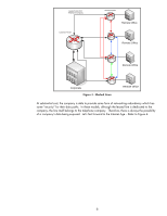
Figure 8 - A Repeater In Figure 8, we see that a repeater sends out an Ethernet packet received on one port to all other ports. You can think of Node "A" as being the wild teenager and Node "F" being the teenager's friend and Nodes "B", "C", "D", and "E" being watchful parents and curious siblings. In short, everyone connected to the hub hears the Ethernet conversation between Node "A" and Node "F". When a house has multiple phone lines with a phone for each line, it is acting a little like an Ethernet Switch. In doing so, it is difficult to listen to other conversations. Refer to Figure 9 - Ethernet Switch. Figure 9 - A Switch Here the Ethernet Switch keeps a table of Ethernet Addresses, also called Media Access Control or MAC addresses. The table is pretty simple - a MAC address or MAC addresses are associated with 11
-
 1
1 -
2
-
3
-
4
-
5
-
 6
6 -
 7
7 -
 8
8 -
 9
9 -
 10
10 -
 11
11 -
 12
12 -
 13
13 -
 14
14 -
 15
15 -
 16
16 -
17
-
18
-
19
-
20
-
21
-
22
-
23
-
24
-
25
-
26
-
27
-
28
-
29
-
30
-
31
-
32
-
33
-
34
-
35
-
36
-
37
-
38
-
39
-
40
-
41
-
42
-
43
-
44
-
45
-
46
-
47
-
48
-
49
-
50
-
51
-
52
-
53
-
54
-
55
-
56
-
57
-
58
-
59
-
60
-
61
-
62
-
63
-
64
-
65
-
66
-
67
-
68
-
69
-
70
-
71
-
72
-
73
-
74
-
75
-
76
-
77
-
78
-
79
-
80
-
81
-
82
-
83
-
84
-
85
-
86
-
87
-
88
-
89
-
90
-
91
-
92
-
93
-
94
-
95
-
96
-
97
-
98
-
99
-
100
-
101
-
102
-
103
-
104
-
105
-
106
-
107
-
108
-
109
-
110
-
111
-
112
-
113
-
114
-
115
-
116
-
117
-
118
-
119
-
120
-
121
-
122
-
123
-
124
-
125
-
126
-
127
-
128
-
129
-
130
-
131
-
132
-
133
-
134
-
135
-
136
-
137
-
138
-
139
-
140
-
141
-
142
-
143
-
144
-
145
-
146
-
147
-
148
-
149
-
150
-
151
-
152
-
153
-
154
-
155
-
156
-
157
-
158
-
159
-
160
-
161
-
162
-
163
-
164
-
165
-
166
-
167
-
168
-
169
-
170
-
171
-
172
-
173
-
174
-
175
-
176
-
177
-
178
-
179
-
180
-
181
-
182
-
183
-
184
-
185
-
186
-
187
-
188
-
189
-
190
-
191
-
192
-
193
 |
 |
