HP Color LaserJet Managed MFP E77822-E77830 On-Site Installation Guide - Page 40
HP LaserJet MFP E72525, E72530, E72535 only
 |
View all HP Color LaserJet Managed MFP E77822-E77830 manuals
Add to My Manuals
Save this manual to your list of manuals |
Page 40 highlights
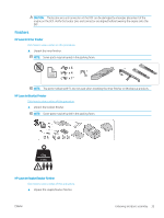
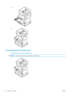
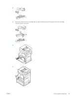
HP LaserJet MFP E72525, E72530, E72535 only The spacer is designed to eliminate the gap between external finishing devices and the engine on E72525, E72530, and E72535 models. Use the casters and stabilizers removed from the DCF on the spacer. Installing the spacer on the DCF, 2000 sheet HCI, or cabinet mono products only (E72525, E72530, E72535) 1. Remove the casters and stabilizers from the bottom of the DCF, 2000 sheet HCI, or cabinet. 2. Install the casters and stabilizers on the spacer. The spacer is necessary on the mono product onlyto allow finishers to be added to the mono device. 3. Place the DCF, 2000 sheet HCI, or cabinet on top of the spacer and secure with two brackets at the rear of the accessory. Installing the engine on the cabinet stand with spacer mono products only (E72525, E72530, E72535) 1. Open two lift bars on the right-side of the engine. CAUTION: The engine assembly is heavy and requires four people to lift. 2. Carefully lift the engine assembly straight up from each corner, align the engine to the locator pins and connector on the cabinet, and then carefully lower the engine onto the DCF, HCI, or cabinet. CAUTION: The locator pins and connector on the cabinet can be damaged by improper placement of the engine on the cabinet. Verify the locator pins and connector are aligned before lowering the engine onto the cabinet. Installing the spacer on the DCF mono products only (E72525, E72530, E72535) 1. Install four casters and screws on the spacer. 2. Install three stabilizers and self-tapping screws on the spacer. 3. Remove two brackets bagged and taped to the spacer. Retain these spacers for installation on the DCF. 4. Carefully place the DCF on the spacer. 5. Install the two brackets and screws in the indents on the right-side of the printer. These are the brackets removed from the bag taped to the DCF. 6. Remove all external/internal tape and all packing materials on the DCF and in the trays. CAUTION: The engine assembly is heavy and requires four people to lift. Installing the engine on the DCF with spacer mono products only (E72525, E72530, E72535) 1. Open two lift bars on the right-side of the engine. CAUTION: The engine assembly is heavy and requires four people to lift. 2. Carefully lift the engine assembly straight up from each corner, align the engine to the locator pins and connector on the DCF, and then carefully lower the engine onto the DCF. 34 Chapter 5 Staging ENWW
-
 1
1 -
2
-
3
-
4
-
5
-
6
-
7
-
8
-
9
-
10
-
11
-
12
-
13
-
14
-
15
-
16
-
17
-
18
-
19
-
20
-
21
-
22
-
23
-
24
-
25
-
26
-
27
-
28
-
29
-
30
-
31
-
32
-
33
-
34
-
 35
35 -
 36
36 -
 37
37 -
 38
38 -
 39
39 -
 40
40 -
 41
41 -
 42
42 -
 43
43 -
 44
44 -
 45
45 -
46
-
47
-
48
-
49
-
50
-
51
-
52
-
53
-
54
-
55
-
56
-
57
-
58
-
59
-
60
-
61
-
62
-
63
-
64
-
65
-
66
-
67
-
68
-
69
-
70
-
71
-
72
-
73
-
74
-
75
-
76
-
77
-
78
-
79
-
80
-
81
-
82
-
83
-
84
-
85
-
86
-
87
-
88
-
89
-
90
-
91
-
92
-
93
-
94
-
95
-
96
-
97
-
98
-
99
-
100
-
101
-
102
-
103
-
104
-
105
-
106
 |
 |
